Material blocking device for optical coupling laser marking machine

A technology of laser marking machine and material blocking device, which is applied in the direction of printing device, printing, etc., can solve the problems of damaging the track structure, difficult adjustment, and reducing strength, etc., and achieves the effect of flexible installation, convenient position adjustment, and no damage to the track

Inactive Publication Date: 2019-12-24
HUBEI KUANGTONG ELECTRONICS
View PDF0 Cites 0 Cited by
  • Summary
  • Abstract
  • Description
  • Claims
  • Application Information

AI Technical Summary

Problems solved by technology

The current method is to open a notch on the track and block the redundant unit modules by sealing the notch with a baffle. The problem is that the structure of the track is destroyed, the strength is reduced, the position of the sealing plate is fixed, it is not easy to adjust, and the efficiency is low. Low

Method used


Image

  • Material blocking device for optical coupling laser marking machine
  • Material blocking device for optical coupling laser marking machine
  • Material blocking device for optical coupling laser marking machine

Examples


Embodiment Construction

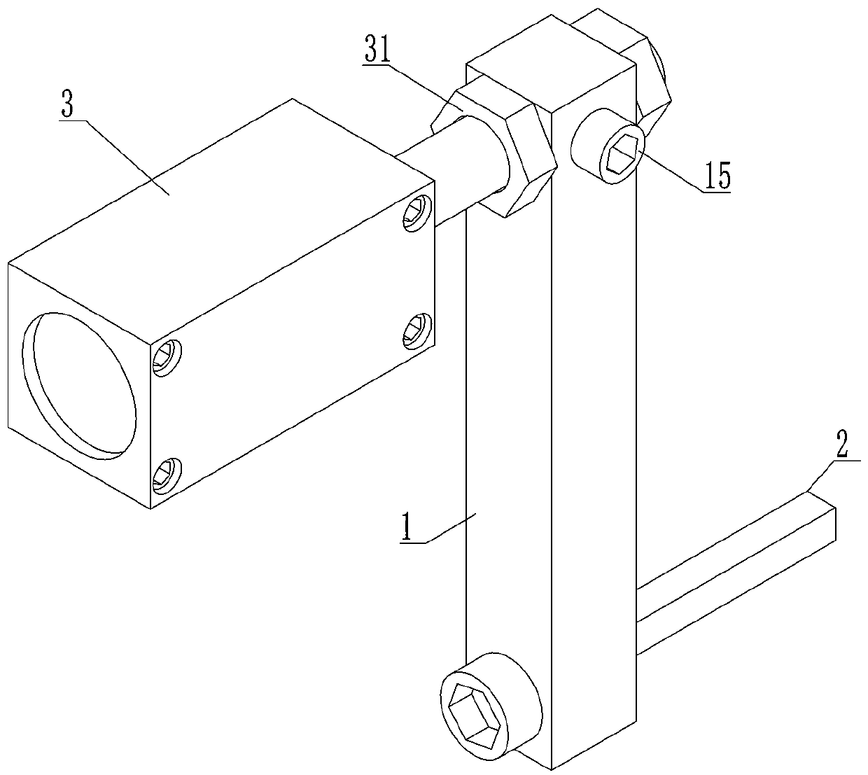
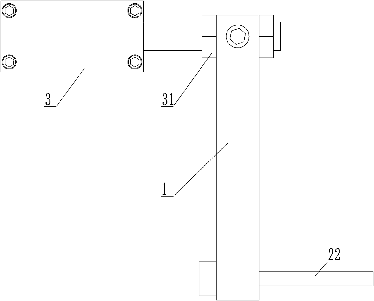
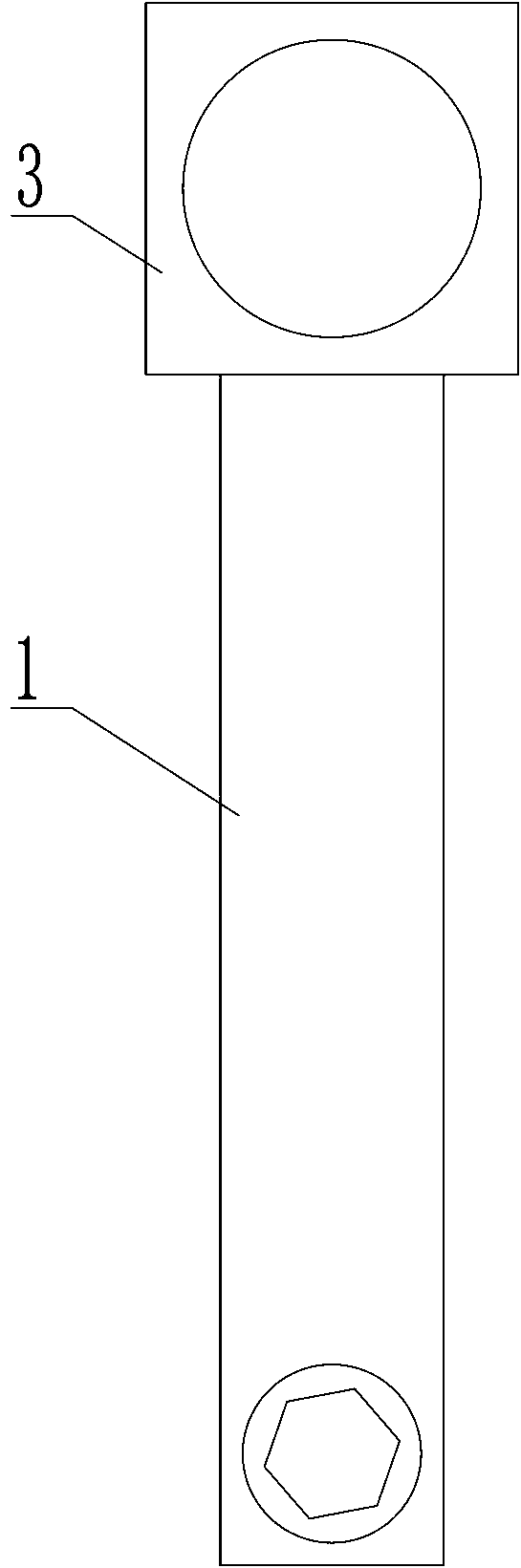
[0027] Such as Figure 1~Figure 6 Among them, an optocoupler laser marking machine stopper device, which includes a vertical rod 1, a stopper rod 2 and a telescopic mechanism 3; the two ends of the vertical rod 1 are respectively connected with the stopper rod 2 and the telescopic mechanism 3; The stopper rod 2 and the telescopic mechanism 3 are located on the same side of the vertical rod 1 or on the two sides corresponding to each other; Tightly connected; the stopper rod 2 and telescopic mechanism 3 on the corresponding two sides are connected with the vertical rod 1 to form a "Z" shape structure. The structure is simple, and the vertical rod 1 is connected to the stopper rod 2 and the telescopic mechanism 3. The stopper rod 2 and the telescopic mechanism 3 are movably connected to the vertical rod 1. The vertical rod 1 is driven to move along the stopper rod 2 through the telescopic mechanism 3. The stopper rod 2 Cooperate with the groove of the marking machine track to b...


PUM


Abstract

The invention discloses a material blocking device for an optical coupling laser marking machine. The device comprises a vertical rod, a material blocking rod and a telescopic mechanism, wherein the material blocking rod is connected to the telescopic mechanism through the vertical rod, and the material blocking rod and the telescopic mechanism are movably connected to the vertical rod; the vertical rod is driven to move along the material blocking rod through the telescopic mechanism, and the material blocking rod cooperates with a groove body of a marking machine track to block a unit module; a clamping nut and a locking screw achieve locking and limiting through rotating of the connecting inclination angle of the vertical rod and the telescopic mechanism; and the connecting position ofthe material blocking rod and the vertical rod is adjusted to match a sliding groove of the track. The material blocking device for the optical coupling laser marking machine overcomes the problems that the track structure is damaged, the adjustment is difficult, and the efficiency is low when a material baffle is installed in an existing optical coupling marking method, and has the characteristics of simple structure, no damage to the track, convenient position adjustment, flexible installation, good adaptability and high efficiency.

Description

technical field [0001] The invention belongs to the technical field of electronic product processing, and relates to a material blocking device for an optocoupler laser marking machine. Background technique [0002] The optocoupler module of the optocoupler electronic display screen is a plate formed by connecting multiple module units when it is a semi-finished product. It is processed and cut into a single independent unit module by punching equipment. After punching, multiple unit modules need to be laser printed. The marked unit module slides into the material tube through the chute on the marking machine slideway. The material tube usually has a certain length and can accommodate a certain number of unit modules. During the continuous sliding of the unit modules, it is necessary to block redundant The unit module enters the material tube. The current method is to open a notch on the track and block the redundant unit modules by sealing the notch with a baffle. The prob...

Claims


Application Information

Patent Timeline
Patent Type & Authority Applications(China)
IPC IPC(8): B41J2/435B41J11/00
CPCB41J2/435B41J11/00
Inventor 秦士英
Owner HUBEI KUANGTONG ELECTRONICS
Why Eureka
Try Eureka