Eureka AIR delivers breakthrough ideas for toughest innovation challenges, trusted by R&D personnel around the world.

Low-voltage direct-current power distribution network and fault isolation method thereof

A low-voltage direct current and distribution network technology, applied in the field of distribution network, can solve problems such as unfavorable power supply reliability and effective isolation of faults, unfavorable development of DC distribution network, and power supply cannot be large short-circuit current, etc., to achieve good engineering application value, The effect of high power supply reliability and low construction cost

Pending Publication Date: 2019-12-24
STATE GRID JIANGSU ELECTRIC POWER CO ELECTRIC POWER RES INST +2
View PDF0 Cites 0 Cited by
  • Summary
  • Abstract
  • Description
  • Claims
  • Application Information

AI Technical Summary

Problems solved by technology

Limited by the fragility of power electronic devices, the power supply composed of them cannot withstand a large short-circuit current in a short period of time like a synchronous machine power supply. At present, power electronic power supplies are immediately blocked within a few milliseconds after a fault occurs to protect the safety of its devices.
The low-voltage distribution network directly faces user loads, and the primary equipment cannot be equipped with more voltage and current transformers for protection discrimination like the transmission network
In the low-voltage DC distribution network, if the power electronic power supply still adopts a short-term blocking strategy for self-protection, it is not conducive to the reliability of power supply and effective isolation of faults, and is not conducive to the development of DC distribution network.

Method used


Image

  • Low-voltage direct-current power distribution network and fault isolation method thereof
  • Low-voltage direct-current power distribution network and fault isolation method thereof

Examples


Embodiment Construction

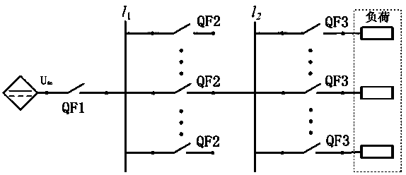
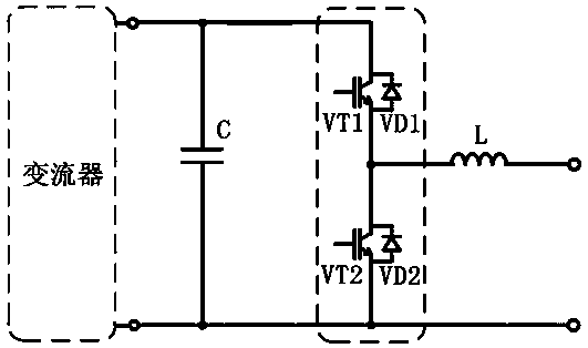
[0023] The low-voltage DC power distribution network provided by the embodiment of the present invention is divided into three levels of lines: power level, intermediate level, and user level. Corresponding switches are configured according to the rated current of the lines at each level. The power supply has low voltage ride-through capability and can be Provide a short-circuit current slightly greater than the rated current for a short period of time to provide tripping current for switches at all levels, and use the tripping characteristics of switches at all levels to construct the protection coordination relationship between the upper and lower lines, which can be effective, reliable, and reliable without power failure in the whole network. Isolate faults quickly.

[0024] The present invention will be further described below in conjunction with the drawings. The following embodiments are only used to illustrate the technical solutions of the present invention more clearly, ...


PUM


Abstract

The invention discloses a low-voltage direct-current power distribution network and a fault isolation method thereof. The low-voltage direct-current power distribution network comprises a power supplylevel line, an intermediate level line and a user level line. The power supply level line comprises a power supply capable of realizing low-voltage ride-through, and a power supply output end is connected with a power supply outlet bus in series. The user level line comprises a direct current load bus which is connected with a third level switch in series to connect an electrical load. The intermediate level line comprises a second level switch which is connected in series between the power supply outlet bus and the direct current load bus. A time difference between a tripping time of the second level switch and a tripping time of the third level switch is at least greater than a tripping time of the third level switch. The tripping time of the second level switch is smaller than a low-voltage ride-through time of the power supply. The tripping current multiple of the second level switch and the tripping current multiple of the third level switch are not smaller than corresponding preset tripping current multiples. According to the method, a fault can be effectively, reliably and rapidly isolated under the condition that a whole network is not powered off.

Description

Technical field [0001] The invention relates to the technical field of power distribution networks, in particular to a low-voltage direct current power distribution network and a fault isolation method thereof. Background technique [0002] At present, a number of DC distribution network demonstration projects have been built in China, but the protection configuration plan of each demonstration project is still formulated with reference to HVDC and flexible DC transmission projects. Transmission grids and distribution grids are significantly different in terms of grid structure and reliable power supply requirements. The low-voltage distribution network adopts the protection configuration scheme of the transmission system, and there are major problems in project cost, scalability and feasibility. Limited by the fragility of power electronic devices, the power supply composed of them cannot withstand large short-circuit currents in a short time like the power supply of synchronous...

Claims


Application Information

Patent Timeline
Patent Type & Authority Applications(China)
IPC IPC(8): H02J1/00H02H7/26
CPCH02J1/00H02H7/268
Inventor 王晨清杨騉李娟孔祥平李鹏高磊陈实齐贝贝
Owner STATE GRID JIANGSU ELECTRIC POWER CO ELECTRIC POWER RES INST
Why Eureka
Eureka Blog
Learn More