Body position constraint device in CT (computed tomography) inspection

A restraint device and body position technology, which is used in patient positioning for diagnosis, medical science, and instruments for radiological diagnosis, etc., can solve the problems of insufficient flexibility and difficult adjustment of the position of the restraint belt, and achieves the effect of high flexibility of the device

Pending Publication Date: 2019-12-27
SHANGHAI TONGJI HOSPITAL
View PDF2 Cites 3 Cited by
  • Summary
  • Abstract
  • Description
  • Claims
  • Application Information

AI Technical Summary

Problems solved by technology

However, because the position of the restraint belt is not easy to adjust, the device is not flexible

Method used


Image

  • Body position constraint device in CT (computed tomography) inspection
  • Body position constraint device in CT (computed tomography) inspection
  • Body position constraint device in CT (computed tomography) inspection

Examples


Embodiment 1

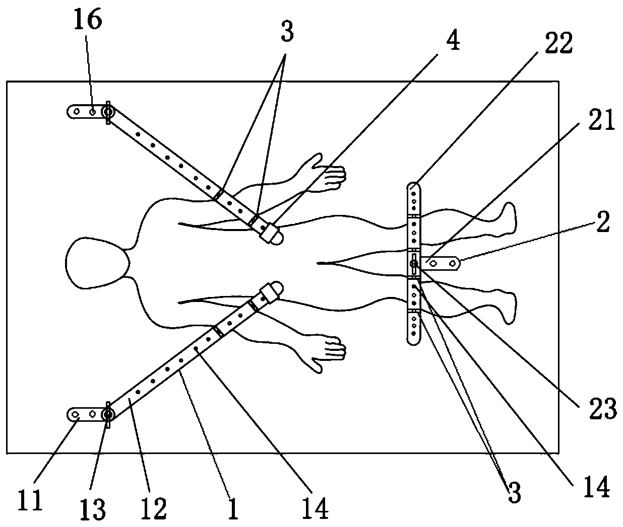
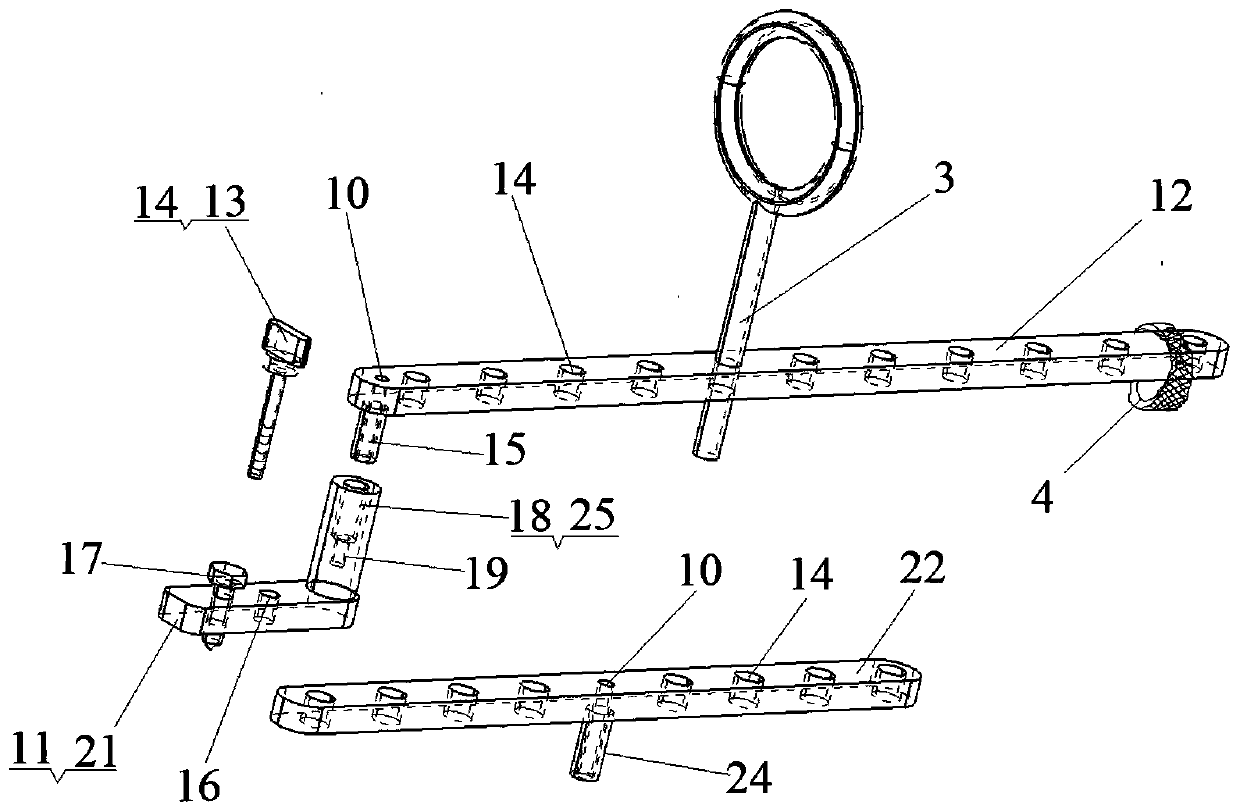
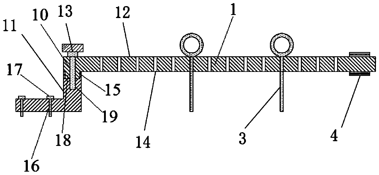
[0040] Please see attached figure 1 , attached figure 2 , with figure 1 It is a schematic diagram of the assembly front plane of a CT examination body position restraint device of the present invention; figure 2It is a three-dimensional schematic diagram of each basic component of a CT examination body position restraint device of the present invention. A posture restraint device for CT examination, comprising two upper limb positioners 1 and one lower limb positioner 2, the upper limb positioner 1 includes an upper fixed base 11, an upper rotating part 12, an upper locking part 13, four limit inserts Rod 3, the upper rotating part 12 is an elongated cylinder structure, and a number of equidistantly distributed limiting holes 14 are arranged on it. The limiting insertion rod 3 is composed of a closed ring and a cylinder, and the cylinder It can pass through the limit hole 14, and one end of the upper rotating part 12 is also provided with a first connecting part 15, and t...

Embodiment 2

[0044] This embodiment is basically the same as Embodiment 1, except that the structure of the upper fixing base 11 and the lower fixing base 21 are different. Please see attached Figure 5 , with Figure 5 It is a cross-sectional schematic diagram of the lower limb positioner described in another CT examination postural restraint device of the present invention. The structure of the lower fixed base 21 becomes a cylinder and is arranged at the center of the flat cylinder. The screw holes 16 on the flat cylinder are symmetrically distributed on both sides of the upper cylinder. The change of its structure does not affect the positioning of the device. and solid performance. This embodiment illustrates that the preferred components of the present application with the same structure may have different structures, subject to the realization of their functions and effectiveness.

Embodiment 3

[0046] Please see attached Figure 6 , with Figure 6 It is a three-dimensional schematic diagram of the upper limb positioner described in another CT examination body position restraint device of the present invention. This embodiment is basically the same as Embodiment 1, the difference is that the upper rotating part 12 is composed of a first body 121 and a second body 122, and the second body 122 slides between the first body 121 connected, and the second body 122 can be hidden inside the first body 121, the position where the second body 122 is connected to the first body 121 is also provided with fastening bolts 123 and corresponding bolt holes 124 ( not shown in the figure), and the second body 122 can overlap and communicate with the limiting hole 14 on the first body 121 . It should be noted that: the upper rotating part 12 is formed by slidingly connecting the first body 121 and the second body 122, and the length of the upper rotating part 12 can be adjusted freel...


PUM


Abstract

The invention belongs to the technical field of medical instruments and relates to a body position constraint device in CT (computed tomography) inspection. The body position constraint device comprises upper limb positioning devices and a lower limb positioning device, wherein the upper limb positioning devices comprise fixing bases, upper rotating parts with limiting holes, upper locking parts and limiting insertion rods; the upper rotating parts are connected with the upper fixing bases through first connecting parts and second connecting parts on the fixing bases in a hinged manner; the lower limb positioning device comprises a lower fixing base, a lower rotating part with limiting holes, a lower locking part and a limiting insertion rod; the lower rotating part is connected with the lower fixing base through a third connecting part and a fourth connecting part on the lower fixing base in a hinged manner; the upper locking parts and the lower locking part are respectively used forfixing the upper rotating parts with the upper fixing bases and the lower rotating part with the lower fixing base; the upper limb positioning devices are symmetrically arranged on both sides of an inspection bed; and the lower limb positioning device is arranged at the middle and lower part of the surface of the inspection bed. The body position constraint device has the advantages of being flexible to use, is capable of implementing flexible position limiting and constraint with active cooperation with the posture of a patient, is simple and easy to operate, and can be mounted and dismountedfreely.

Description

technical field [0001] The invention relates to the technical field of medical devices, in particular to a CT examination body restraint device Background technique [0002] During CT examination, in order to ensure the quality of the examination, the patients to be examined usually need to lie on the CT bed stably for the examination, but some patients are irritable and easy to move or move around unconsciously, which is extremely easy to cause image artifacts, thus affecting the examination Quality even caused the inspection to fail. Therefore, it is very necessary to restrain the limbs of such patients. However, the existing CT examination bed with restraint function has certain limitations, requiring the patient to actively cooperate with the position of the corresponding fixing device to fasten it, which is not flexible enough, increases the discomfort of the patient, makes the patient more resistant, and brings great inconvenience to the medical staff. Great inconven...

Claims


Application Information

Patent Timeline
IPC IPC(8): A61B6/04A61B6/03
CPCA61B6/03A61B6/0421
Inventor 韩砆石王未陈淑珍王程弘王恒礼
Owner SHANGHAI TONGJI HOSPITAL
Why Eureka
Try Eureka