Supercharge Your Innovation With Domain-Expert AI Agents!

Sander

A technology of sanding machine and bottom plate, which is applied in the field of sanding machines, can solve problems such as hand fatigue, unbalanced sanding machine, and large vibration amplitude of flat sand, so as to reduce fatigue, enhance user experience, and reduce the size of the whole machine. effect of size

Pending Publication Date: 2019-12-27
NANJING CHERVON IND
View PDF0 Cites 0 Cited by
  • Summary
  • Abstract
  • Description
  • Claims
  • Application Information

AI Technical Summary

Problems solved by technology

[0004] At present, the common problem of existing sanding machines is: the eccentric movement of the base plate makes the sanding machine in an unbalanced state, which causes the vibration of the whole sanding machine, and the user is easy to feel hand fatigue when operating for a long time , and cannot control the sanding machine very well, especially the flat sand has a large vibration amplitude, the sanding machine needs to preset a certain space for the user to hold during operation

Method used


Image

  • Sander
  • Sander
  • Sander

Examples


Embodiment Construction

[0033] The technical solutions of the present invention will be further described below in conjunction with the accompanying drawings and through specific implementation methods.

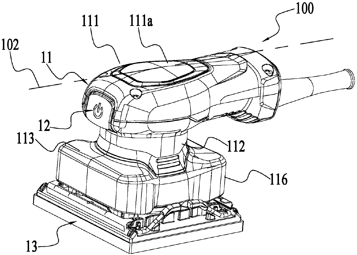
[0034] like figure 1 The sander 100 shown at least includes: a housing 11 , a switch 12 , a bottom plate assembly 13 , a control mechanism 14 , a power mechanism and a connecting bracket 16 .

[0035] Wherein, the casing 11 is used as the exterior part of the sander 100 , and it is formed with a gripping portion 111 , a first accommodating portion 112 , a mounting portion 113 and a surrounding portion 116 . The grip part 111 is used for gripping by the user, and is located above the entire sander 100 . It is in the shape of a flat ring. The first accommodating portion 112 is located between the grip portion 111 and the surrounding portion 116 , and a first accommodating cavity is formed inside. The surrounding part 116 forms a height space for accommodating the connecting bracket 16 , and the moun...


PUM

PropertyMeasurementUnit
Heightaaaaaaaaaa

Abstract

The invention discloses a sander. The sander comprises a bottom plate assembly, motors, a shell and a connecting bracket, wherein the bottom plate assembly comprises a bottom plate which forms a bottom plate plane; the motors are used for driving the bottom plate assembly to move; the shell forms an accommodating part for accommodating at least part of the motors; the bottom plate can move relative to the shell with a longitudinal axis as a center when being driven by the motors; the connecting bracket is arranged between the bottom plate assembly and the shell and connects the bottom plate assembly and the shell to limit the movement of the bottom plate assembly relative to the shell to a certain range; the size of the sander in the direction parallel to the longitudinal axis is less thanor equal to 120 mm; and the connecting bracket comprises a first connecting part connected with the shell, a second connecting part connected with the bottom plate, and a flexible connecting leg which is arranged between the first connecting part and the second connecting part and respectively connects the first connecting part and the second connecting part. According to the sander, shock absorption of the whole sander is achieved through the connecting bracket, the size of the whole sander is reduced through reasonable arrangement of the heights of the connecting bracket and the whole sander, and user experience is improved.

Description

technical field [0001] The invention relates to the technical field of sanding equipment, in particular to a sander. Background technique [0002] A sander is a mechanical device used to complete sanding work. Sanding is a synonym for grinding, which refers to processing some materials and objects that are uneven, uneven in thickness, or do not meet the process requirements into standard parts with smooth surface, uniform thickness, and meeting various process requirements through mechanical equipment. Optomechanics are widely used in many fields such as machinery and home decoration. [0003] The sander mainly includes a motor, a transmission assembly and a bottom plate assembly, among which the transmission assembly contains an eccentric. In the working state, the transmission assembly transmits the rotational motion of the motor into the eccentric motion of the bottom plate. Sandpaper or other grinding parts are installed on the lower surface of the bottom plate, and t...

Claims


Application Information

Patent Timeline
IPC IPC(8): B24B23/00B24B41/00
CPCB24B23/00B24B41/007
Inventor 陈治国
Owner NANJING CHERVON IND
Features
  • R&D
  • Intellectual Property
  • Life Sciences
  • Materials
  • Tech Scout
  • Unparalleled Data Quality
  • Higher Quality Content
  • 60% Fewer Hallucinations
Learn More