High-temperature in-situ fretting-fatigue experimental system

A fretting fatigue, experimental system technology, applied in the direction of applying repetitive force/pulsation force to test the strength of materials, measuring devices, instruments, etc., can solve the problems of easy failure of test pieces, reduction of structural life of fasteners, and damage of structural parts.

Pending Publication Date: 2019-12-27
EAST CHINA UNIV OF SCI & TECH
View PDF0 Cites 1 Cited by
  • Summary
  • Abstract
  • Description
  • Claims
  • Application Information

AI Technical Summary

Problems solved by technology

The failure caused by fretting fatigue occurs widely in various industrial fields, which will accelerate the damage of structural parts and lead to a significant decrease in the structural life of some fasteners, which is one of the important reasons for the damage of structural parts
And under the action of high temperature, the specimen is more easily damaged
[0003] Most of the existing test devices adopt unidirectional loading, and seldom consider the load cross effect; at the same time, none of the existing test devices can realize the in-situ observation of dovetail single-point and multi-point fretting contact conditions, in order to explore the friction and wear in fretting fatigue The essential failure mechanism starts from the microscopic in-situ observation to solve the failure problem of mechanical parts caused by fretting fatigue in engineering. It is necessary to provide a high-temperature in-situ fretting fatigue experiment system

Method used


Image

  • High-temperature in-situ fretting-fatigue experimental system
  • High-temperature in-situ fretting-fatigue experimental system
  • High-temperature in-situ fretting-fatigue experimental system

Examples


Embodiment Construction

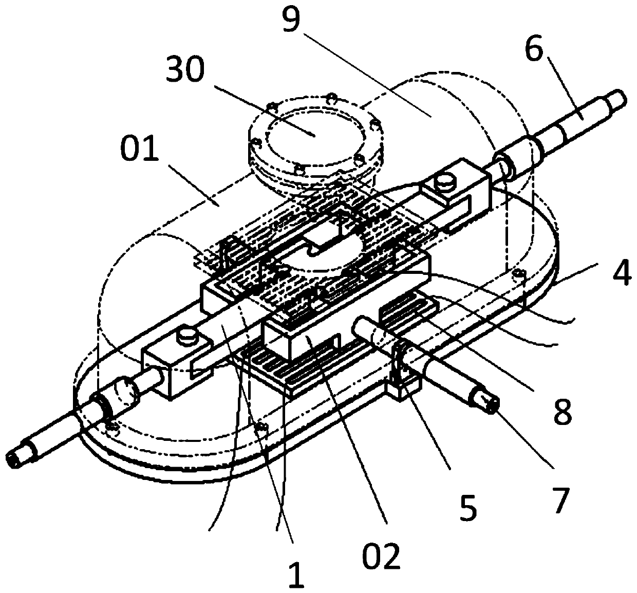
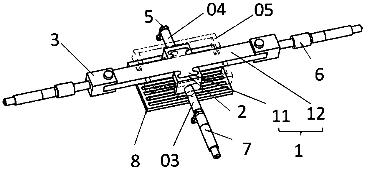
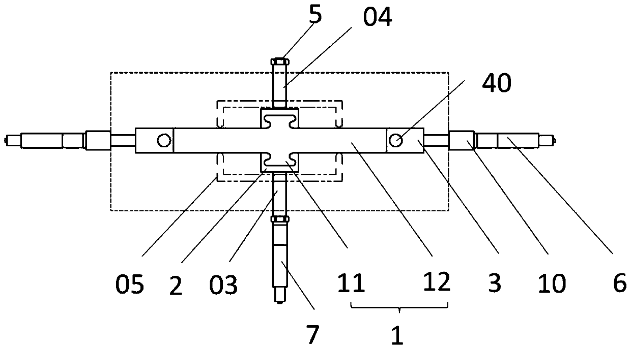
[0056]The specific implementation of the high-temperature in-situ fretting fatigue test system of the present invention is given below in conjunction with the accompanying drawings, but it should be pointed out that the specific implementation is not intended to limit the specific implementation of the present invention. All similar structures and similar changes using the present invention should be included in the protection scope of the present invention. The following description of the embodiments refers to the accompanying drawings to illustrate specific embodiments in which the invention may be practiced. The directional terms mentioned in the embodiments, such as "up", "down", "front", "rear", "left", "right", "top", "bottom", etc., are only for reference to the accompanying drawings direction. Therefore, the directional terms used are used to illustrate and understand the present invention, but not to limit the present invention.

[0057] see figure 1 , figure 1 I...


PUM


Abstract

The invention relates to a high-temperature in-situ fretting-fatigue experimental system. The high-temperature in-situ fretting-fatigue experimental system comprises a test piece, a fretting-fatigue clamp, an extreme environment room, a base, a support base, a fretting stretching device, a fretting-fatigue loading device and a heating device; the test piece comprises a test section and a connection section; the test section is a dovetail joint structural part; the test section has two relatively arranged test surfaces; the connection section has two second contact planes; the fretting-fatigueclamp comprises a first clamp, a second clamp and a fretting bridge; an opened containing groove is arranged at one end; a friction surface is arranged in the containing groove; the containing grooveis used for containing the test section; the test surface and the friction surface are in surface contact; the second clamp is connected with the connection section and the fretting stretching device;the fretting bridge comprises a first fretting bridge and a second fretting bridge; the first fretting bridge is a flat fretting bridge; the second fretting bridge is a semi-cylindrical fretting bridge or a hemispherical fretting bridge; and the fretting-fatigue loading device is connected with the first clamp or the flat fretting bridge along the normal direction of the dovetail joint structuralpart of the test part.

Description

technical field [0001] The invention relates to the field of high-temperature material performance testing, in particular to a high-temperature in-situ fretting fatigue experiment system. Background technique [0002] Under the coupling action of cross-amplitude changing loads such as force vibration and temperature cycle change, the contact surfaces of fastened mechanical parts will undergo relative motion with a displacement amplitude on the order of microns, which is called fretting. The fretting between the contact surfaces of structural parts will promote the generation of cracks, crack propagation and even fracture at the damaged part. This process is called fretting fatigue. The failure caused by fretting fatigue occurs widely in various industrial fields, which will accelerate the damage of structural parts and lead to a significant decrease in the structural life of some fasteners, which is one of the important reasons for the damage of structural parts. And under ...

Claims


Application Information

Patent Timeline
Patent Type & Authority Applications(China)
IPC IPC(8): G01N3/32G01N3/04
CPCG01N3/04G01N3/32G01N2203/0005G01N2203/0017G01N2203/0073G01N2203/0226G01N2203/0244G01N2203/04G01N2203/0676
Inventor 王宁朱金龙张显程刘利强张佳敏涂善东
Owner EAST CHINA UNIV OF SCI & TECH
Why Eureka
Try Eureka