

Ratio electrochemical detection method of ochratoxin A
An ochratoxin and detection method technology, applied in the field of biosensing, can solve the problems of electrochemical sensors being easily interfered by external factors, low reliability accuracy, insufficient accuracy, etc., and achieves high reliability, improved reliability and high reliability. Accuracy and high sensitivity
- Summary
- Abstract
- Description
- Claims
- Application Information
AI Technical Summary
Benefits of technology
Problems solved by technology
Method used
Image

Examples
Embodiment 1
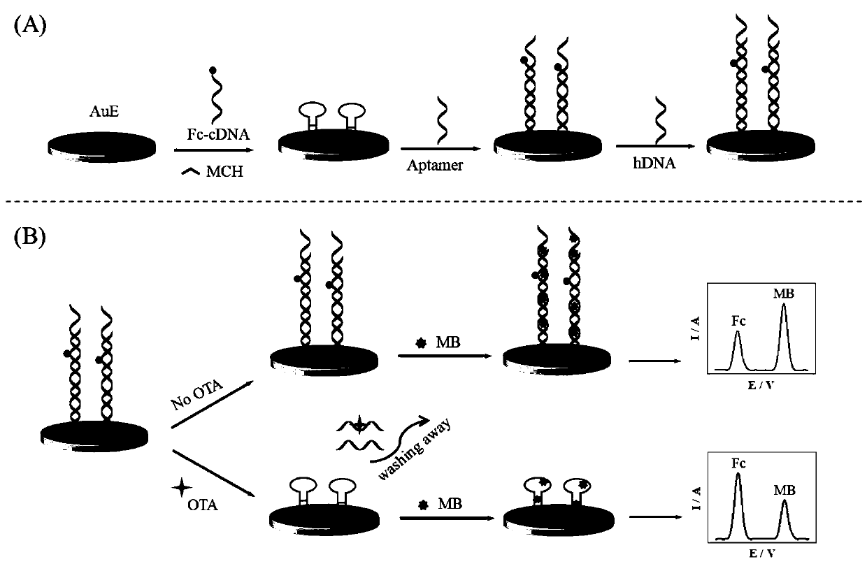
[0034] A ratiometric electrochemical detection method for ochratoxin A, comprising the following steps:
[0035] (1) Grind a gold electrode (AuE) with a diameter of 3mm with 0.3μm and 0.05μm Al2O3 powder in turn, and ultrasonically clean the surface residue in ethanol and water in turn, and then in 0.1M sulfuric acid solution at 100mV / s The scanning speed, the potential of -0.2-1.6V use cyclic voltammetry to electrochemically clean the electrode;
[0036] (2) Modify 6 μL of ferrocene-labeled complementary DNA (Fc-cDNA) with a concentration of 1 μM onto the electrode treated in step (1), place it at room temperature for 8 hours, and use Au-S bonds to fix Fc-cDNA on the gold electrode surface;
[0037](3) 6 μL of mercaptohexanol (MCH) with a concentration of 1 mM was modified on the electrode treated in step (2), and incubated at room temperature for 1 hour to block the non-specific binding site of gold;
[0038] (4) Modify 6 μL of ochratoxin A aptamer (Aptamer) with a concent...
PUM
| Property | Measurement | Unit |
|---|---|---|
| Diameter | aaaaa | aaaaa |
Abstract
Description
Claims
Application Information