Exhalation valve arrangement for ventilator apparatus with apparatus for receiving pressure sensor

A technology of breathing equipment and exhalation valve, which is applied in the direction of valve devices, respirators, mechanical equipment, etc., and can solve problems affecting feasibility, structural errors, and not so effective

Active Publication Date: 2019-12-27
HAMILTON MEDICAL AG
View PDF17 Cites 2 Cited by
  • Summary
  • Abstract
  • Description
  • Claims
  • Application Information

AI Technical Summary

Problems solved by technology

However, structural errors between the measuring point of the breathing gas pressure at the proximal end of the exhalation line and the measuring point close in the valve assembly, but located upstream thereof, affect the feasibility, e.g. The elasticity of the expiratory hose of the expiratory line of the gas valve arrangement causes the pressure measurement at the proximal end of the expiratory line to be relevant for the expiratory line actually present in the upstream respiratory gas channel upstream of the valve assembly. The breathing gas pressure in the distal region of the

Method used


Image

  • Exhalation valve arrangement for ventilator apparatus with apparatus for receiving pressure sensor
  • Exhalation valve arrangement for ventilator apparatus with apparatus for receiving pressure sensor
  • Exhalation valve arrangement for ventilator apparatus with apparatus for receiving pressure sensor

Examples


Embodiment Construction

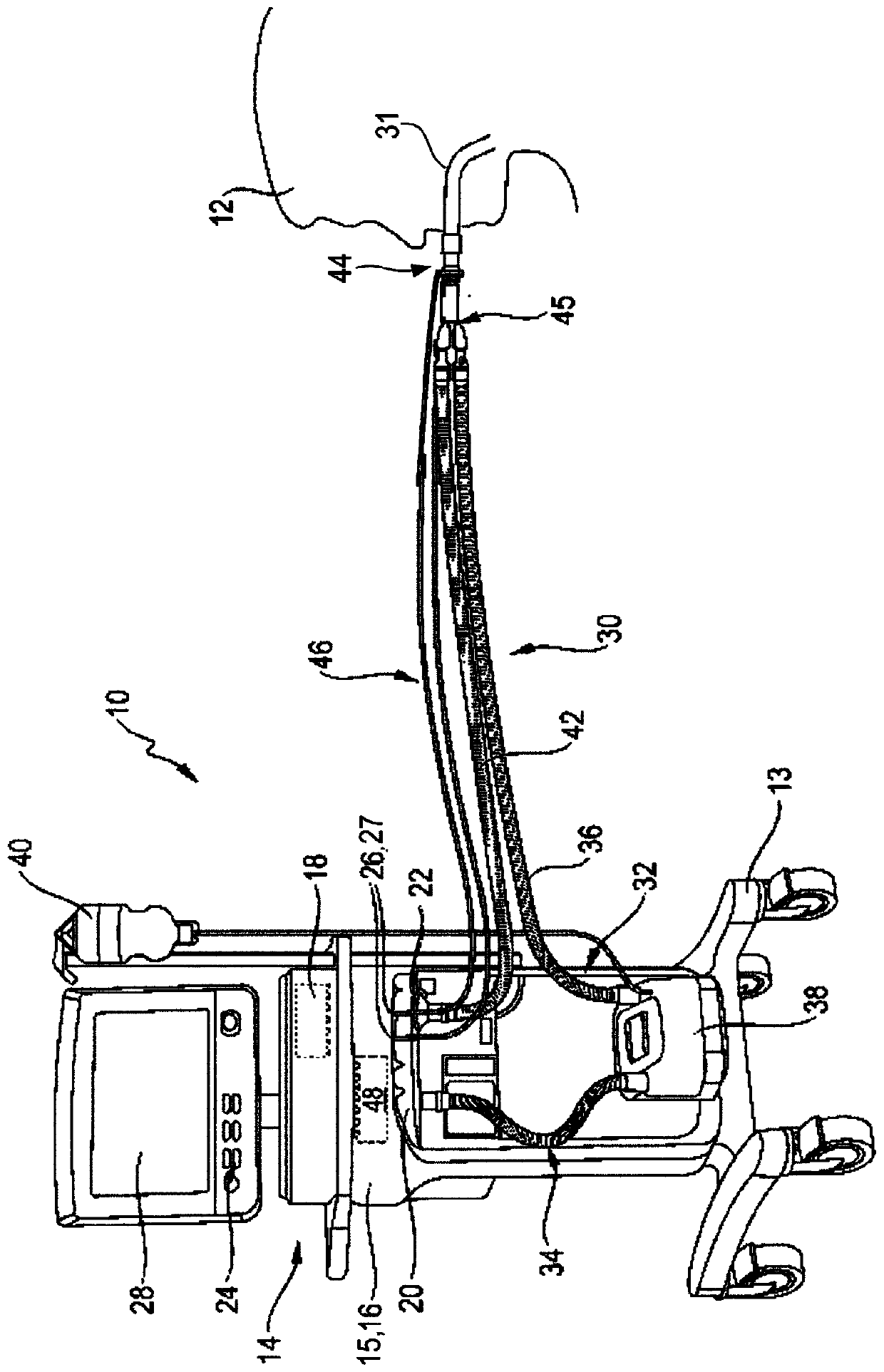
[0054] In order to illustrate the exhalation valve device according to the present invention, it should first be based on figure 1 Describes respiratory equipment using exhalation valve devices.

[0055] exist figure 1 In , breathing equipment is generally represented by 10. In the example shown, the breathing device 10 is used for artificial respiration of a human patient 12 . The breathing device 10 can be accommodated as a mobile breathing device 10 on a rollable stand 13 .

[0056] The breathing device 10 has a housing 14 in which—due to the opaque housing material, it is not visible from the outside—a pressure varying device 16 and a control device 18 can be accommodated.

[0057] The pressure variation device 16 is designed in a manner known per se and has a breathing gas supply device 15 in the form of a pump, compressor or fan, which can be controlled in a variable manner in each case so as not only to Gas is introduced into the breathing apparatus and serves to va...


PUM


Abstract

An exhalation valve device (22) for a ventilator apparatus for the artificial respiration of patients can be flowed through in an exhalation flow direction (E) and comprises: an upstream breathing gasduct (54), which extends along a first duct path (K1) and is or can be connected to a section of the exhalation line coming from the patient, a downstream breathing gas duct (58), which extends alonga second duct path (K2) and is or can be connected to a breathing gas sink (U), a valve assembly (63) having a valve body (64) and a valve seat (66), which valve assembly is provided between the upstream and the downstream breathing gas ducts (54, 58) such that, in the event of a predetermined first breathing gas overpressure in the upstream gas duct (54) relative to the downstream gas duct (58),the valve assembly permits an exhalatory breathing gas flow from the upstream breathing gas duct (54) to the downstream breathing gas duct (58) and, in the event of a predetermined second breathing gas overpressure in the downstream breathing gas duct (58) relative to the upstream breathing gas duct (54), the valve assembly blocks a gas flow from the downstream breathing gas duct (58) to the upstream breathing gas duct (54). According to the invention, the exhalation valve arrangement (22) has a bypass chamber (74) that communicates via flow mechanics with the upstream breathing gas duct (54)and extends from the upstream breathing gas duct (54) to the region of the downstream breathing gas duct (58) and there is designed for coupling a gas pressure sensor (80).

Description

technical field [0001] The invention relates to an exhalation valve device of an exhalation circuit of a breathing apparatus for performing artificial respiration on a patient, wherein the exhalation valve device is permeable along the exhalation flow direction and comprises: [0002] - an upstream breathing gas channel which extends along the first channel path and which is or can be connected to the section of the expiratory line which originates from the patient, [0003] - a downstream breathing gas channel which extends along the second channel path and which is connected or connectable to a breathing gas outlet, for example the external environment, [0004] - a valve assembly having a valve body and a valve seat, the valve assembly being arranged between the upstream breathing gas passage and the downstream breathing gas passage such that the valve assembly is relatively opposite to the downstream breathing gas in the upstream expiratory gas passage a flow of exhaled b...

Claims


Application Information

Patent Timeline
Patent Type & Authority Applications(China)
IPC IPC(8): A61M16/20A61M16/08A61M16/00
CPCA61M16/0816A61M16/208A61M16/0858A61M16/206F16K1/523F16K7/17
Inventor 卡洛琳·弗兰克费利克斯·布赖特鲁克
Owner HAMILTON MEDICAL AG
Why Eureka
Try Eureka