Autonomous driving control system for vehicles
An automatic driving control and automatic driving technology, which is applied in the traffic control system, traffic control system, anti-collision system, etc. of road vehicles, and can solve problems such as inability to operate safely, loss of power supply, and various failures
- Summary
- Abstract
- Description
- Claims
- Application Information
AI Technical Summary
Problems solved by technology
Method used
Image

Examples
no. 1 approach
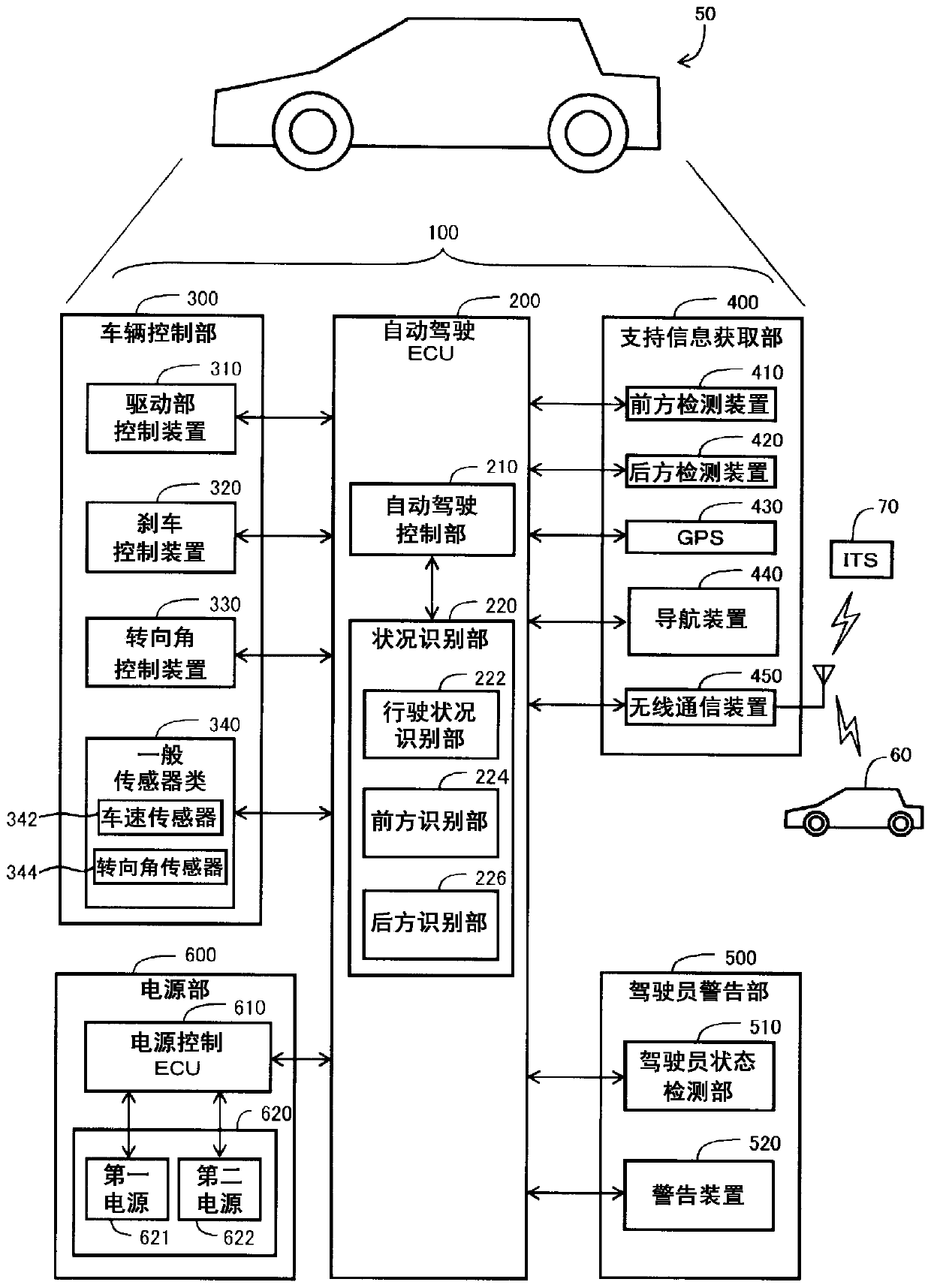
[0034] Such as figure 1 As shown, the vehicle 50 of the first embodiment includes an automatic driving control system 100 . The automatic driving control system 100 includes an automatic driving ECU 200 (Electronic Control Unit: Electronic Control Unit), a vehicle control unit 300 , a support information acquisition unit 400 , a driver warning unit 500 , and a power supply unit 600 . In addition, in this specification, the vehicle 50 is also called "own vehicle 50".
[0035] The automatic driving ECU 200 is a circuit including a CPU and a memory. The automatic driving ECU 200 functions to control the automatic driving of the vehicle 50 as the automatic driving control unit 210 by executing the computer program stored in the nonvolatile storage medium, and also functions to recognize the situation related to the vehicle 50 as the situation recognition unit 220 . . The function of the situation recognition unit 220 will be described in detail later.
[0036] The vehicle cont...
no. 2 approach
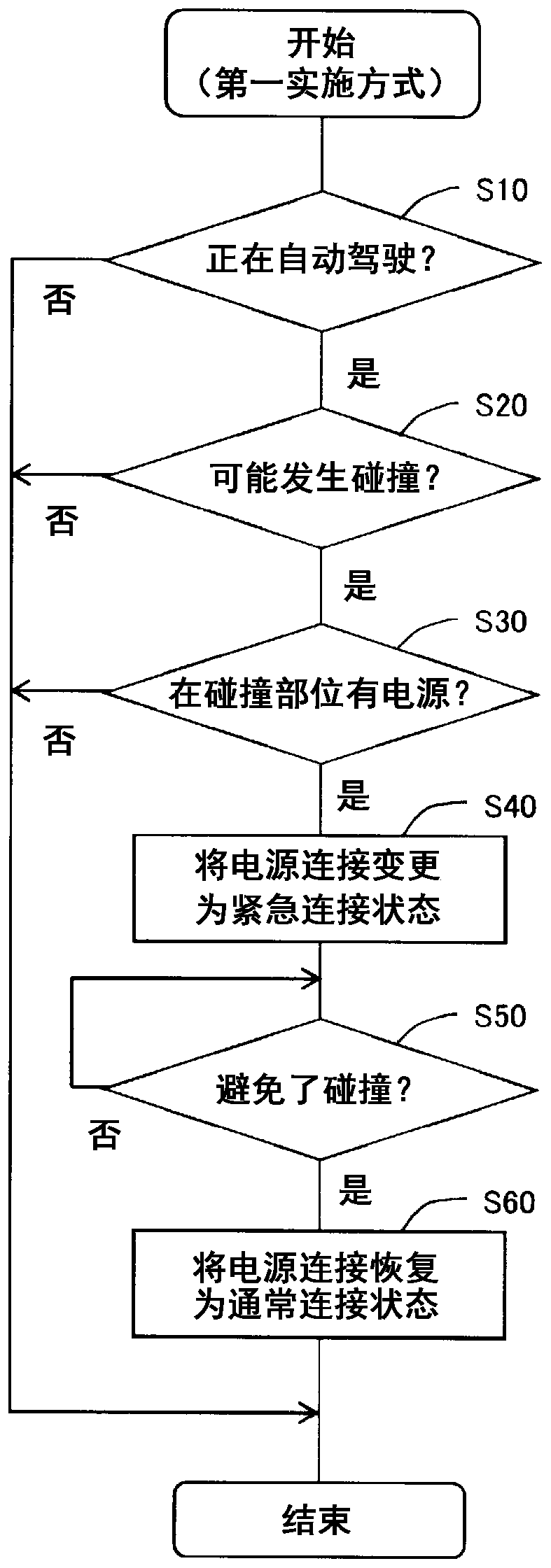
[0058] Such as Figure 5 As shown, the steps of the power supply connection change processing in the second embodiment are as follows: image 3 Steps S120 and S130 are added between step S40 and step S50, and steps S150 and S160 are added after step S60. In addition, in Figure 5 In the processing procedure of , when step S30 makes a negative judgment, it proceeds to step S120 described later.
[0059] In steps S120 and S130, when the host vehicle 50 temporarily stops or runs slowly near the center of the intersection, if the situation recognition unit 220 recognizes the preset steering angle change situation, the automatic driving control unit 210 will follow the predetermined steering angle change situation. The first steering angle of the traveling route (the first steering angle indicated by the steering angle indication value for automatic driving) is changed to a different second steering angle to alleviate the influence of the host vehicle 50 being rear-ended by anoth...
no. 3 approach
[0075] Such as Figure 9 As shown, in the third embodiment, step S120 ( Figure 5 ) The detailed steps of judging the steering angle change status are the same as those of the second embodiment ( Figure 6 ) are different, but Figure 5 The overall procedure of the shown power supply connection change process is the same as that of the second embodiment. That is, in the third embodiment, with Figure 5 steps to perform the overall power connection change process, to Figure 9 The detailed steps to execute Figure 5 The judgment of step S120.
[0076] Figure 9 and Figure 6 The difference is that step S300 is added between step S220 and step S230. In step S300, it is determined whether or not a preset rear collision condition is satisfied. When the rear collision condition is satisfied, the process proceeds to step S230 , and the status recognition unit 220 recognizes the steering angle change status. On the other hand, if the rear collision condition is not satisfie...
PUM
 Abstract
Description
Claims
Application Information
 - R&D
- Intellectual Property
- Life Sciences
- Materials
- Tech Scout
- Unparalleled Data Quality
- Higher Quality Content
- 60% Fewer Hallucinations
Browse by: Latest US Patents, China's latest patents, Technical Efficacy Thesaurus, Application Domain, Technology Topic, Popular Technical Reports.
© 2025 PatSnap. All rights reserved.Legal|Privacy policy|Modern Slavery Act Transparency Statement|Sitemap|About US| Contact US: help@patsnap.com