Fixing clamp for touch screen processing

A technology for fixing fixtures and touch screens, applied in manufacturing tools, workpiece clamping devices, etc., can solve the problems of easy movement of workpieces and poor use stability, and achieve the effect of reducing workpiece displacement and improving use stability.

Inactive Publication Date: 2019-12-31
JIANGSU DIJIA ELECTRONICS CO LTD
View PDF7 Cites 2 Cited by
  • Summary
  • Abstract
  • Description
  • Claims
  • Application Information

AI Technical Summary

Problems solved by technology

[0002] As we all know, the touch screen processing fixture is an auxiliary device used for fixing the touch screen during processing, and it has been widely used in the field of electronic processing equipment; the existing touch screen processing fixture includes a workbench, a fixed base, a bolt , dead point clamping device, pressing handle, pressing rod and rubber pressure head. A fixed base is arranged on the front side of the upper end of the workbench. The bolts are screwed through the fixed base and inserted into the upper end of the workbench. The upper end of the fixed base is tightly attached, and the upper end of the fixed base is provided with a dead point clamping device. The pressing handle and the pressing rod are installed inside the dead point clamping device. There is a hinge point at the intersection of the pressing handle and the pressing rod. When the points are on the same straight line, the dead point clamping device is at the dead point position, the workpiece is clamped, and a rubber pressure head is arranged on the outermost side of the lower end of the pressure rod, and the rubber pressure head is screwed on the pressure rod; the existing touch screen processing fixed fixture uses , firstly wipe the upper end of the workbench clean, then place the workpiece on the upper end of the workbench, then press the handle, which drives the pressure rod down through the hinge point until the clamping device is at the dead point. The rod can be pressed against the workpiece by the rubber pressure head; in the use of the existing touch screen processing fixture, it is found that the one-point pressing fastening method makes the workpiece easy to move, resulting in poor stability in use

Method used


Image

  • Fixing clamp for touch screen processing
  • Fixing clamp for touch screen processing
  • Fixing clamp for touch screen processing

Examples


Embodiment Construction

[0017] The specific implementation manners of the present invention will be further described in detail below in conjunction with the accompanying drawings and embodiments. The following examples are used to illustrate the present invention, but are not intended to limit the scope of the present invention.

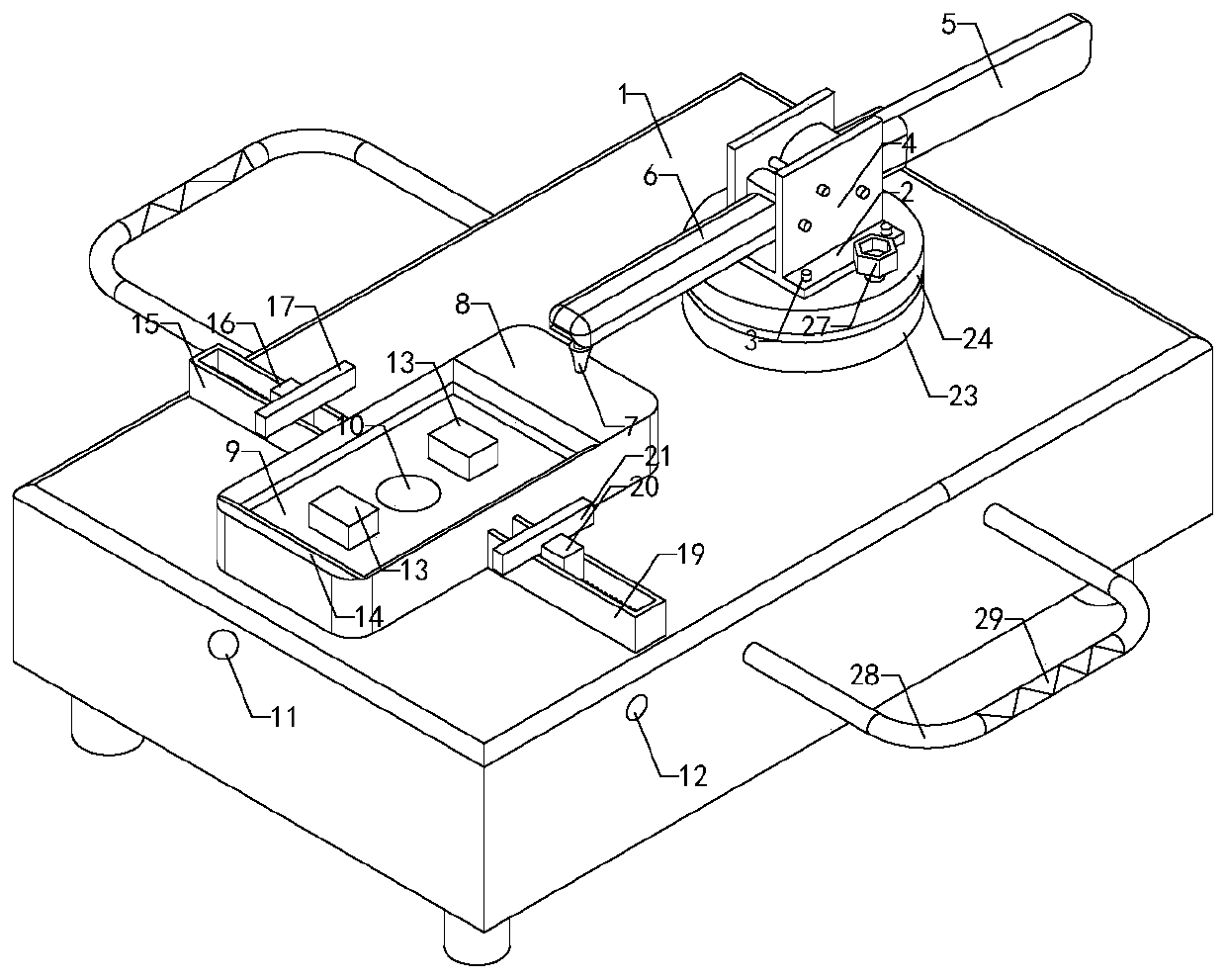
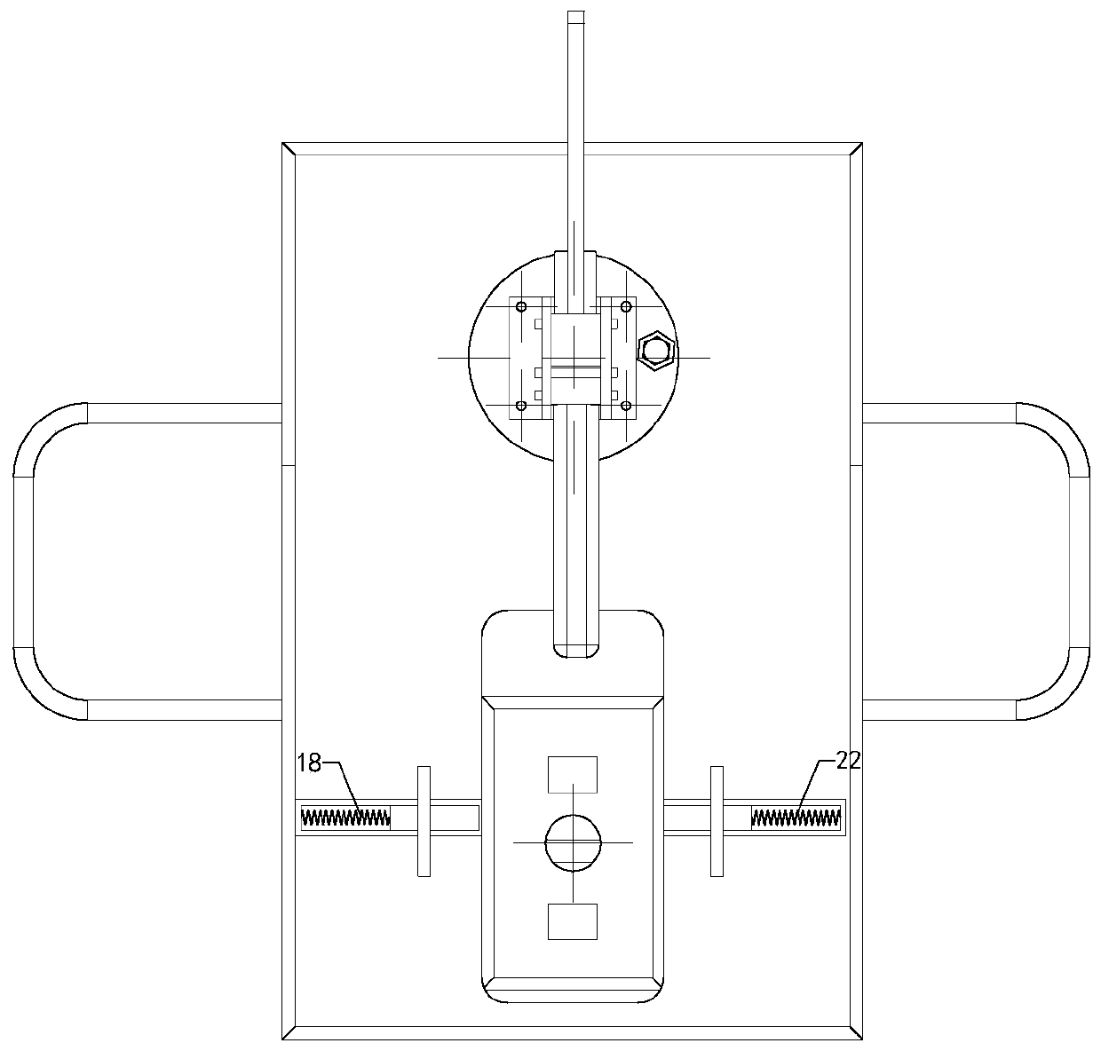
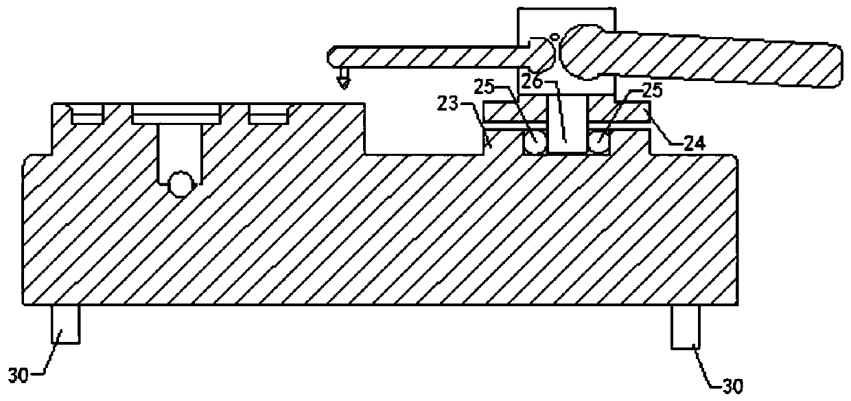
[0018] Such as Figure 1 to Figure 3 As shown, a touch screen processing fixing fixture of the present invention firstly wipes the upper end of the workbench 1 clean, then places the workpiece on the upper end of the workbench 1, and then presses the pressing handle 5, which drives the pressing rod 6 times through the hinge point Press until the clamping device 4 is at the dead point, and the pressure rod 6 can press the workpiece through the rubber pressure head 7; it also includes a vacuum table 8, a vacuum suction groove 9, a vacuum suction hole 10, and an air extraction hole. 11. The rubber pad 13 and the sealing ring 14, the vacuum table 8 is set in the middle of the...


PUM


Abstract

The invention relates to the technical field of electronic processing equipment, in particular to a fixing clamp for touch screen processing. The fixing clamp firmly adsorbs a workpiece, reduces the displacement phenomenon of the workpiece and improves the use stability. Firstly, the upper end of a workbench is wiped, the workpiece is placed at the upper end of the workbench, a pressing handle ispressed, the pressing handle drives a pressing rod to press down through a hinged point until a dead point clamping device is pressed to a dead point position, and the workpiece is pressed by the pressing rod through a rubber pressing head. The fixing clamp further comprises a vacuum workbench, a vacuum adsorption groove, a vacuum adsorption hole, an air exhaust hole, a rubber cushion block and asealing ring, the vacuum workbench is arranged in the middle of the upper end of the workbench, the upper end of the vacuum workbench is provided with the vacuum adsorption groove, the center of the upper end of the vacuum adsorption groove is provided with the vacuum adsorption hole, the upper end of the vacuum adsorption groove is provided with the rubber cushion block, the sealing ring is installed on the edge of the vacuum adsorption groove, the front end of the workbench is provided with the air exhaust hole, and the air exhaust hole communicates with the vacuum adsorption hole.

Description

technical field [0001] The invention relates to the technical field of electronic processing equipment, in particular to a touch screen processing fixture. Background technique [0002] As we all know, the touch screen processing fixture is an auxiliary device used for fixing the touch screen during processing, and it has been widely used in the field of electronic processing equipment; the existing touch screen processing fixture includes a workbench, a fixed base, a bolt , dead point clamping device, pressing handle, pressing rod and rubber pressure head. A fixed base is arranged on the front side of the upper end of the workbench. The bolts are screwed through the fixed base and inserted into the upper end of the workbench. The upper end of the fixed base is tightly attached, and the upper end of the fixed base is provided with a dead point clamping device. The pressing handle and the pressing rod are installed inside the dead point clamping device. There is a hinge point...

Claims


Application Information

Patent Timeline
Patent Type & Authority Applications(China)
IPC IPC(8): B25B11/00
CPCB25B11/005
Inventor 万国春杨纪辉蔡国武胡克
Owner JIANGSU DIJIA ELECTRONICS CO LTD
Why Eureka
Try Eureka