Stator wire ingot wiring crimping equipment

A technology of crimping equipment and stator wire, which is applied in the field of crimping equipment for stator wire ingot wiring, can solve the problems of slow work efficiency, easy displacement of thread ends, and low work efficiency, so as to improve production efficiency, reduce the displacement of thread ends, The effect of easy operation

Inactive Publication Date: 2021-02-09
HUZHOU YUEQIU MOTOR
View PDF0 Cites 0 Cited by
  • Summary
  • Abstract
  • Description
  • Claims
  • Application Information

AI Technical Summary

Problems solved by technology

[0002] Stator wire ingot refers to the stator frame wound with winding groups. In some special motor applications, it is necessary to ensure that the outlet of the wire ingot is connected in place, and to press the terminal into the outlet and cut off the excess wire. At present, only manual operation can be used to complete the above operations. When manual operation is performed, not only the work efficiency is slow, but also the thread head is prone to displacement and jumps out of the wiring groove.
Therefore, the existing technology has the problems of low work efficiency and easy displacement of the thread head

Method used


Image

  • Stator wire ingot wiring crimping equipment
  • Stator wire ingot wiring crimping equipment

Examples


Embodiment Construction

[0013] The present invention will be further described below in conjunction with the accompanying drawings and embodiments, but not as a basis for limiting the present invention.

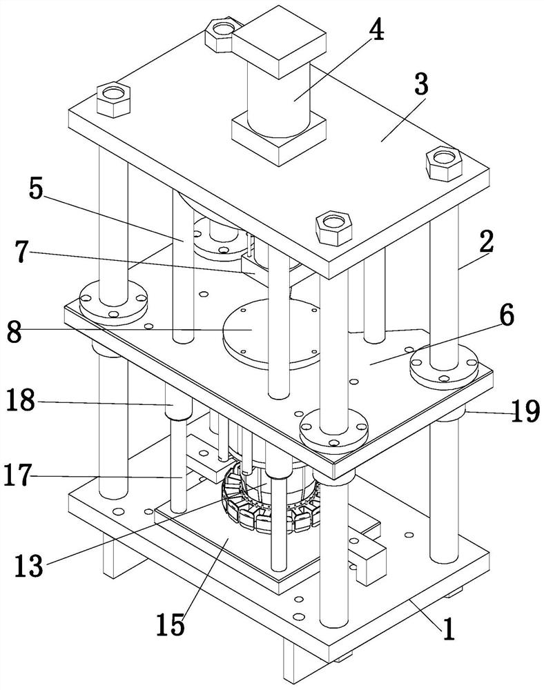
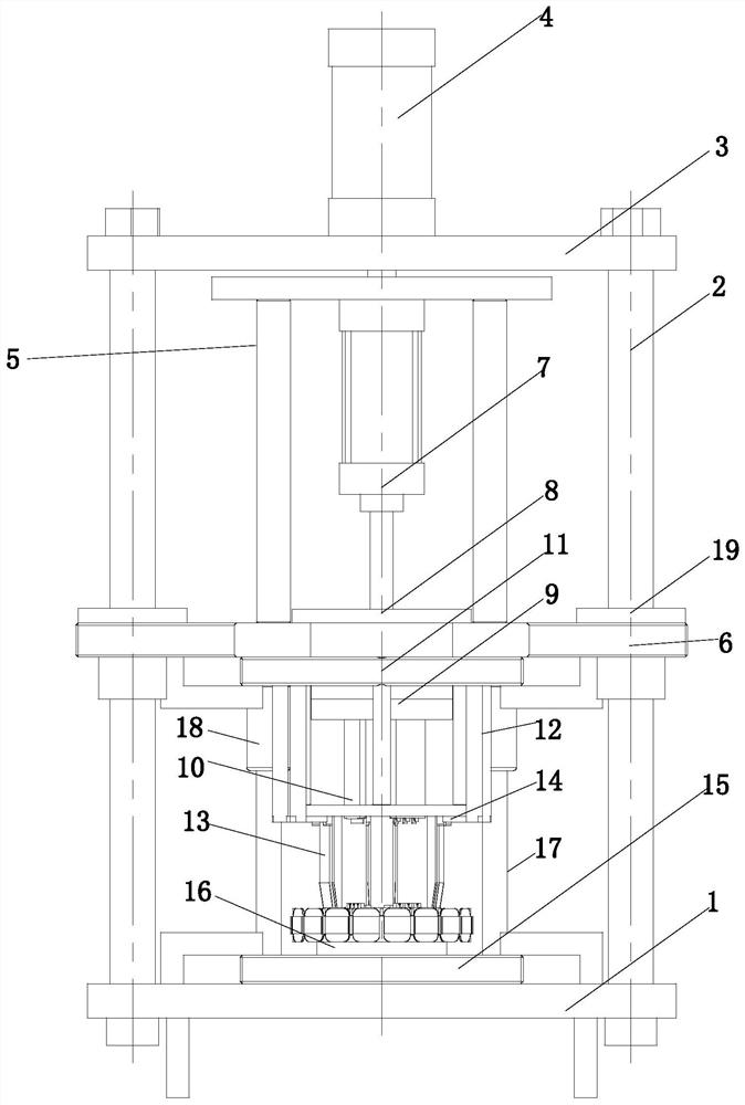
[0014] Example. A stator wire ingot wiring crimping equipment, constituted as follows Figure 1 to Figure 2 As shown, including a base 1, a guide column 2 is provided above the base 1, a top plate 3 is provided at the upper end of the guide column 2, a top cylinder 4 is provided above the top plate 3, and a receiving frame 5 located below the top plate 3 is provided at the output end of the top cylinder 4. The lower end of the receiving frame 5 is provided with a middle slide plate 6 sleeved on the guide column 2, the receiving frame 5 is provided with a cutting cylinder 7, the output end of the cutting cylinder 7 is provided with a backing plate 8, and the bottom of the backing plate 8 is provided with a fixing plate 9, Fixed plate 9 below is provided with blade group 10; Also comprises the chess ...


PUM


Abstract

The invention discloses stator wire ingot wiring crimping equipment which comprises a base, a guide column arranged above the base, a top plate arranged at the upper end of the guide column, a top aircylinder arranged above the top plate, a bearing frame arranged at the output end of the top air cylinder and located below the top plate, a middle sliding plate arranged at the lower end of the bearing frame in a sleeving mode, and a cutting air cylinder arranged on the bearing frame. A base plate is arranged at the output end of the cutting air cylinder, a fixing plate is arranged below the base plate, and a blade set is arranged below the fixing plate; the equipment also comprises a chess frame top plate fixed below the middle sliding plate, a supporting rod set located on the outer side of a cutter set is arranged below the chess frame top plate, a pressing ring matched with the cutter set is arranged below the supporting rod set, and a thread shifting rod set located on the outer side of the supporting rod set is further arranged below the chess frame top plate; a chess frame bottom plate is arranged on the upper surface of the base, and a thread spindle limiting seat is arrangedin the middle of the chess frame bottom plate. The equipment has the characteristics that the working efficiency can be effectively improved, and the displacement phenomenon of thread ends is reduced.

Description

technical field [0001] The invention relates to a stator wire ingot production equipment, in particular to a stator wire ingot wire crimping equipment. Background technique [0002] Stator wire ingot refers to the stator frame wound with winding groups. In some special motor applications, it is necessary to ensure that the outlet of the wire ingot is connected in place, and to press the terminal into the outlet and cut off the excess wire. At present, only manual operation can be used to complete the above operations. When manual operation is performed, not only the work efficiency is slow, but also the thread head is prone to displacement and jumps out of the wiring groove. Therefore, the existing technology has the problems of low work efficiency and easy displacement of the thread head. Contents of the invention [0003] The purpose of the present invention is to provide a stator wire ingot crimping equipment. The invention has the characteristics of effectively impro...

Claims


Application Information

Patent Timeline
IPC IPC(8): H02K15/00
CPCH02K15/0062
Inventor 邵明元陈峰李会芳顾炜标金波费利明边树军陈昱罗荣福松尾繁唐章俊陈彦达王韬
Owner HUZHOU YUEQIU MOTOR
Why Eureka
Try Eureka