Charging equipment power distribution method, storage medium and system

A charging equipment and distribution method technology, applied in charging stations, electric vehicle charging technology, electric vehicles, etc., can solve the problem of low utilization rate of charging equipment

Active Publication Date: 2019-12-31
BEIJING DIDI INFINITY TECH & DEV
View PDF4 Cites 10 Cited by
  • Summary
  • Abstract
  • Description
  • Claims
  • Application Information

AI Technical Summary

Problems solved by technology

[0003] The embodiment of the present invention aims to provide a charging equipment power distribution method, storage medium

Method used


Image

  • Charging equipment power distribution method, storage medium and system
  • Charging equipment power distribution method, storage medium and system
  • Charging equipment power distribution method, storage medium and system

Examples


Embodiment 1

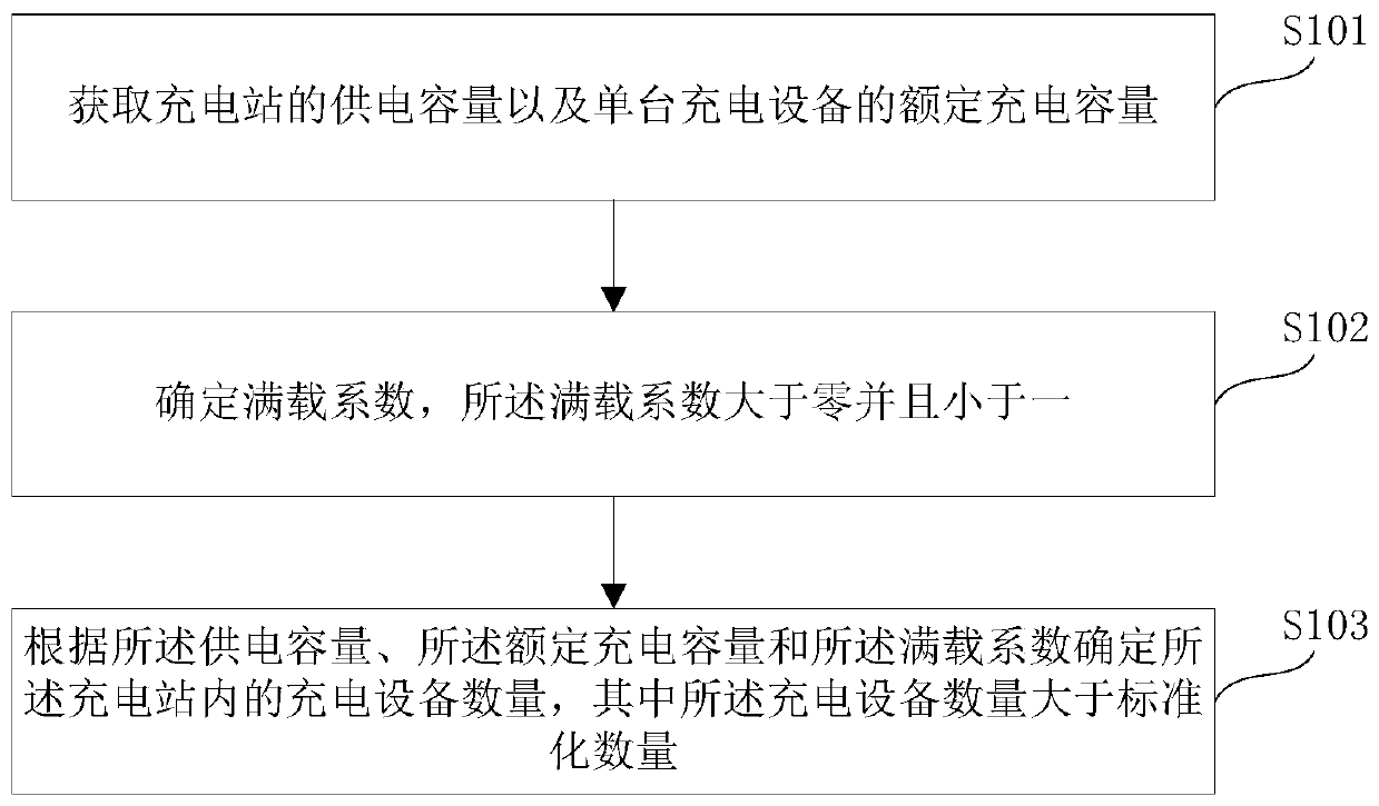
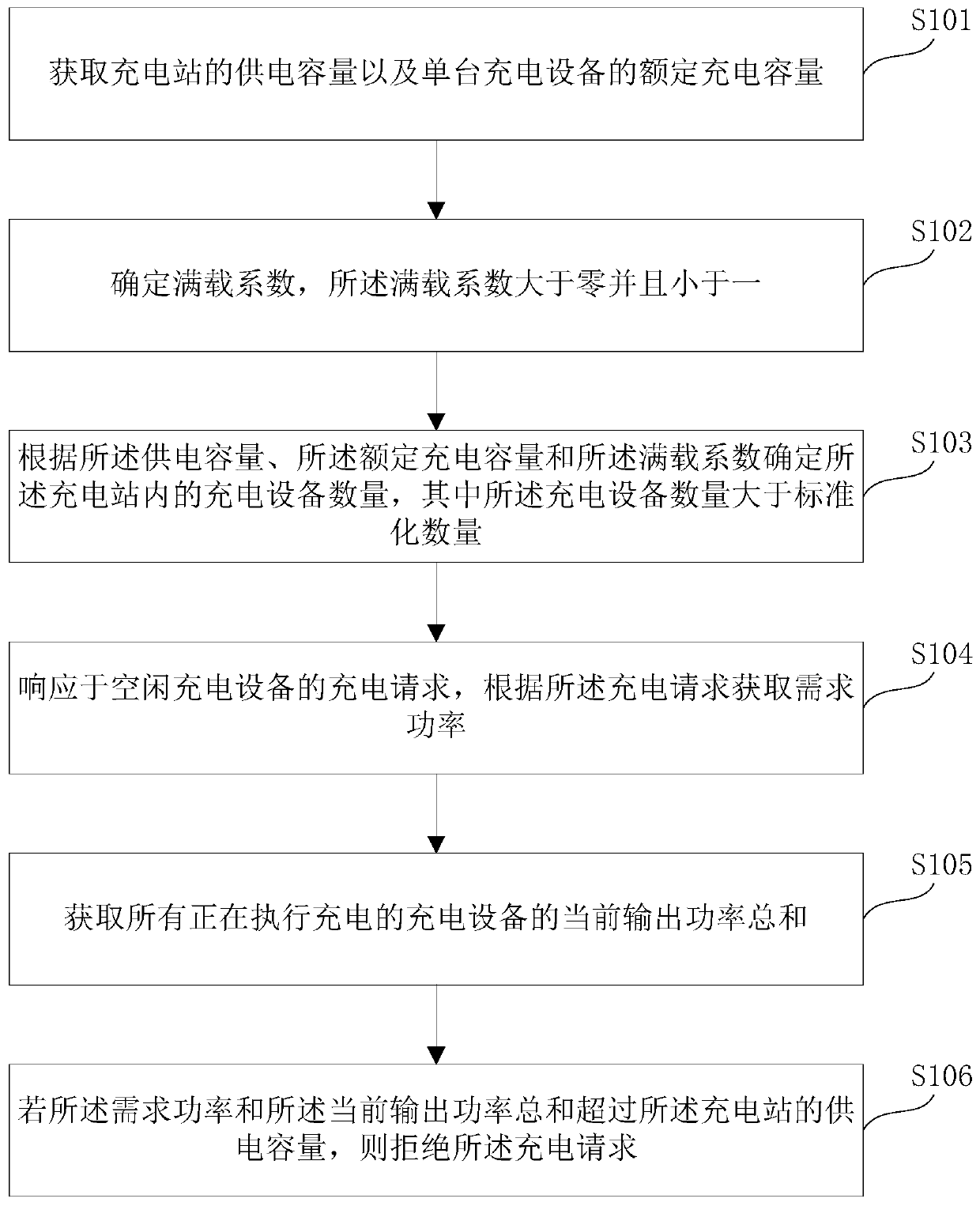
[0049] This embodiment provides a charging equipment power distribution method, which can be applied to the control system of the existing charging station, such as figure 1 As shown, it includes the following steps:

[0050] S101: Obtain the power supply capacity of the charging station and the rated charging capacity of a single charging device; it can be determined at the beginning of designing the charging station.

[0051] S102: Determine the full load factor, the full load factor is greater than zero and less than one; it can be determined according to historical experience, such as referring to the traffic flow and charging demand at the location of the charging station, preferably between 0.6-0.9, preferably can be Choose 0.7 and 0.8. Preferably, the number of charging devices is determined by the following method: M=|P Z / (Q×P K )|; where, Q is the full load factor. Where | | means to take an integer and discard the decimal, for example, P Z / (Q×P K )=13.5, the ...

Embodiment 2

[0077] This embodiment provides a storage medium, wherein program instructions are stored in the storage medium, and after the computer reads the program instructions, it executes the charging device power allocation method described in any one of the technical solutions in Embodiment 1.

Embodiment 3

[0079] Figure 5 It is a schematic diagram of the hardware structure of the electronic device implementing the charging device power distribution method provided in this embodiment, and the device includes:

[0080] one or more processors 501 and memory 502, Figure 5 A processor 501 is taken as an example. The device for executing the power allocation method for charging equipment may further include: an input device 503 and an output device 504 . The processor 501, the memory 502, the input device 503 and the output device 504 may be connected via a bus or in other ways, Figure 5 Take connection via bus as an example.

[0081] The memory 502, as a non-volatile computer-readable storage medium, can be used to store non-volatile software programs, non-volatile computer-executable programs and modules. The processor 501 executes various functional applications and data processing of the server by running non-volatile software programs, instructions and modules stored in th...


PUM


Abstract

The invention provides a charging equipment power distribution method, a storage medium and a system. The charging equipment power distribution method comprises the steps of obtaining power supply capacity of a charging station and a rated charging capacity of single charging equipment; determining a charge ratio, wherein the charge ratio is larger than 0 and less than 1; determining the number ofcharging equipment in the charging station according to the power supply capacity, the rated charging capacity and the charge ratio, wherein the number of the charging equipment is larger than a standardized number N; and the standardized number N satisfies that N is equal to the absolute value of PZ/PK, the PZ is the power supply capacity, and the PK is the rated charging capacity of the singlecharging equipment. According to the technical scheme of the charging equipment power distribution method, as the mounting number of charging piles in the charging station is increased, more vehiclescan be charged in the case that the multiple charging piles all do not work at the rated charging capacity so that the charging capacity can be more reasonably distributed to each charging pile in thecase of limited power grid power distribution power; and therefore, maximum use efficiency of the power distribution power can be guaranteed, and the use safety of the power distribution power is also guaranteed.

Description

technical field [0001] The invention relates to the technical field of charging station design, and in particular to a charging equipment power distribution method, storage medium and system. Background technique [0002] With the increasing popularity of new energy vehicles, the demand for charging has become more and more vigorous, and more and more charging stations have been built. However, the power distribution of charging stations generally has a capacity limit. The grid power distribution power of a charging station It is impossible to expand at will. For a charging station, the capacity of the power supply has a maximum capacity, and then the charging station configures an appropriate number of charging devices according to the maximum capacity. In the prior art scheme, the maximum capacity is approximately equal to the number and The product of the charging rated power of each charging device. For example, the capacity of the power supply is 1250KVA, and there ar...

Claims


Application Information

Patent Timeline
IPC IPC(8): B60L53/62B60L53/30B60L53/00
CPCB60L53/62B60L53/30B60L53/00Y02T90/14
Inventor 许令波余海琳盛捷
Owner BEIJING DIDI INFINITY TECH & DEV
Why Eureka
Try Eureka