Clutch pressure plate

A clutch and pressure plate technology, applied in clutches, friction clutches, mechanical drive clutches, etc., can solve the problems of reduced contact area between pressure plate and friction plate, reduced torque transmission capacity, uneven heat distribution, etc., to achieve smooth engagement and less rigidity. The effect of deformation and high heat dissipation efficiency

Inactive Publication Date: 2019-12-31
JIANGSU UNIV
View PDF11 Cites 0 Cited by
  • Summary
  • Abstract
  • Description
  • Claims
  • Application Information

AI Technical Summary

Problems solved by technology

Due to the frequent gear shifting of the clutch, the friction system will generate a lot of heat. Due to the difference in the linear velocity of the inner and outer diameters of the pressure plate, the generated heat will be unevenly distributed, and the pressure plate will be thermally deformed, resulting in a decrease in the actual contact area between the pressure plate and the friction plate. The torsion transmission capacity decreases, and even permanent deformation, cracking and ablation of the pressure plate occur.
[0003] Through the calcul

Method used


Image

  • Clutch pressure plate
  • Clutch pressure plate

Examples


Example Embodiment

[0026] The present invention will be further described below in conjunction with the drawings and specific embodiments, but the protection scope of the present invention is not limited to this.

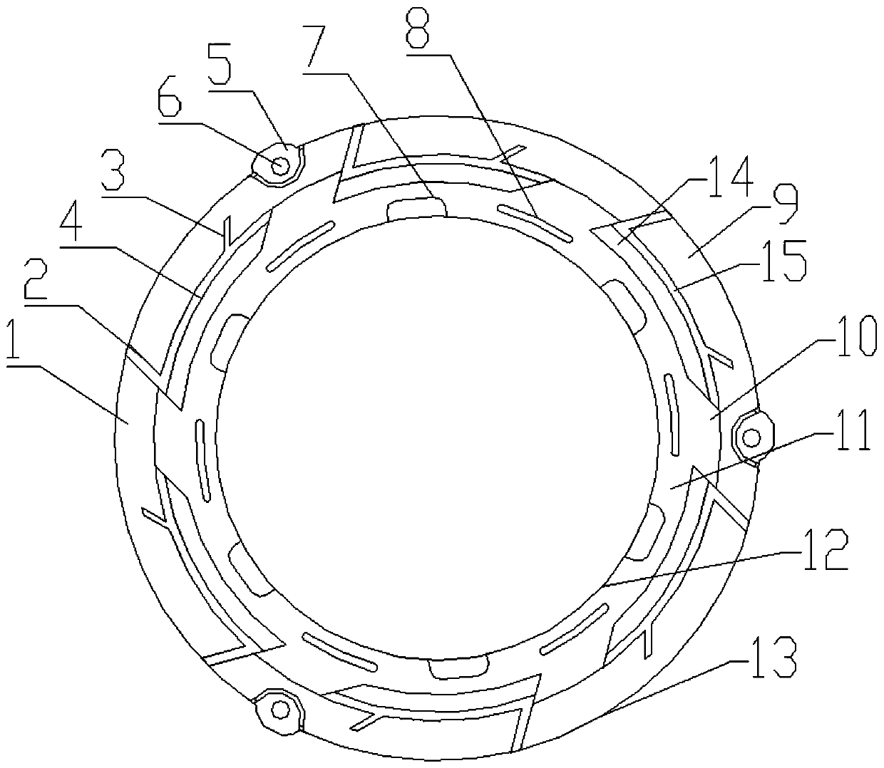
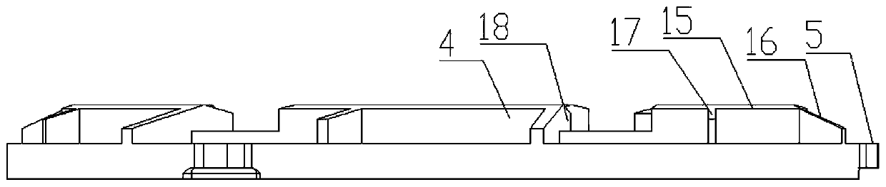
[0027] Such as figure 1 , 2 As shown, the clutch pressure plate of the present invention includes a pressure plate body 1, a long reinforcing rib 2, a short reinforcing rib 3, a pressure plate tooth 4, a lug 5, a mounting hole 6, a U-shaped groove 7, a U-shaped heat sink Hole 8, the pressure plate main body 1 is annular, the end surface of the pressure plate main body 1 is provided with several pressure plate teeth 4 evenly distributed in the circumferential direction, and the part from the pressure plate teeth 4 to the outer diameter 13 of the pressure plate main body 1 Is the outer ring 9 of the pressure plate, and the part from the pressure plate teeth 4 to the inner diameter 12 of the pressure plate body 1 is the inner ring 11 of the pressure plate; the pressure plate teeth 4 are prov...


PUM

PropertyMeasurementUnit
Apertureaaaaaaaaaa
Groove depthaaaaaaaaaa

Abstract

The invention provides a clutch pressure plate which comprises a pressure plate body, long reinforcing ribs, short reinforcing ribs, pressure plate teeth, convex lugs, mounting holes, U-shaped groovesand U-shaped heat radiation through holes. The multiple pressure plate teeth are arranged on the end face of the pressure plate body. The long reinforcing ribs and the short reinforcing ribs are located on the outer sides of the pressure plate teeth. The convey lugs are evenly distributed on the outer diameter of the pressure plate in the circumferential direction, and the mounting holes are formed in the center positions of the convex lugs. The U-shaped grooves are distributed on the inner diameter of the pressure plate, the U-shaped heat radiation through holes are distributed in the middleposition of the inner ring of the pressure plate, and the U-shaped heat radiation through holes and the U-shaped grooves are sequentially arranged at intervals. By means of the long reinforcing ribsand the short reinforcing ribs, the strength of the clutch pressure plate can be improved; by means of the heat radiation grooves and the heat radiation holes, the heat radiation performance of the clutch pressure plate can be improved; the power performance of the clutch pressure plate can be improved well through the rotating directions of the long reinforcing ribs, the short reinforcing ribs and the end faces of the pressure plate teeth; and thus, the clutch pressure plate has the advantages that rigidity is large, deformation is not prone to happening, the heat radiation efficiency is high, the heat radiation effect is good, the power transmission efficiency is high, high temperature resisting is achieved, smoothness is good, and the service life is long.

Description

technical field [0001] The invention relates to the technical field of clutch manufacturing, in particular to a clutch pressure plate. Background technique [0002] The clutch pressure plate is an important component used for clutch power transmission. The pressure plate, the engine flywheel and the friction plate together form a friction system. When the clutch is engaged, the diaphragm spring pushes the pressure plate to make it contact with the friction plate, and through relative friction Gradually cling to complete the engagement. Due to the frequent gear shifting of the clutch, the friction system will generate a lot of heat. Due to the difference in the linear velocity of the inner and outer diameters of the pressure plate, the generated heat will be unevenly distributed, and the pressure plate will be thermally deformed, resulting in a decrease in the actual contact area between the pressure plate and the friction plate. The torsion transmission capacity decreases, ...

Claims


Application Information

Patent Timeline
IPC IPC(8): F16D13/70F16D13/72
CPCF16D13/70F16D13/72
Inventor 司俊领朱茂桃
Owner JIANGSU UNIV
Why Eureka
Try Eureka