A gyroscope array calibration method and system

A calibration method, gyroscope technology, applied in the direction of measuring devices, instruments, etc.

Active Publication Date: 2020-08-28
ROCKET FORCE UNIV OF ENG
View PDF5 Cites 0 Cited by
  • Summary
  • Abstract
  • Description
  • Claims
  • Application Information

AI Technical Summary

Problems solved by technology

However, the above methods are all to calibrate a single gyro, and the accuracy of a single gyro is much worse than that of a gyro array.

Method used


Image

  • A gyroscope array calibration method and system
  • A gyroscope array calibration method and system
  • A gyroscope array calibration method and system

Examples


Embodiment Construction

[0053] The following will clearly and completely describe the technical solutions in the embodiments of the present invention with reference to the accompanying drawings in the embodiments of the present invention. Obviously, the described embodiments are only some, not all, embodiments of the present invention. Based on the embodiments of the present invention, all other embodiments obtained by persons of ordinary skill in the art without making creative efforts belong to the protection scope of the present invention.

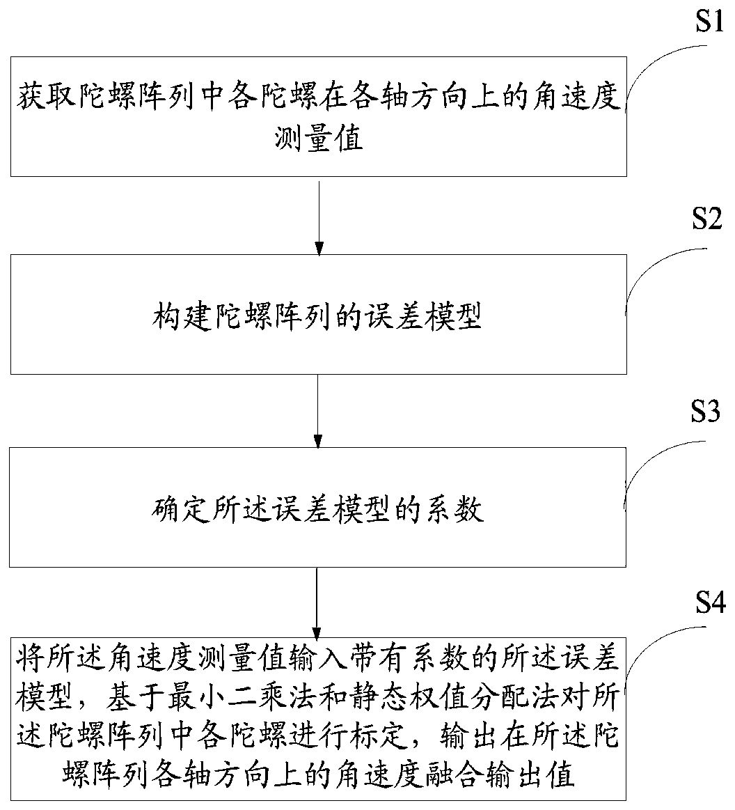
[0054] The purpose of the present invention is to provide a gyro array calibration method and system to improve the output accuracy of the gyro array.

[0055] In order to make the above objects, features and advantages of the present invention more comprehensible, the present invention will be further described in detail below in conjunction with the accompanying drawings and specific embodiments.

[0056] The zero offset error of the microelectromechanical g...


PUM


Abstract

The invention discloses a gyroscope array calibration method and system. The method comprises the following steps: acquiring an angular velocity measurement value of each gyroscope in a gyroscope array in each axis direction; determining a coefficient of an error model; constructing an error model of the gyroscope array; and inputting the angular velocity measurement values into the error model with the coefficient, calibrating the gyroscopes in the gyroscope array based on a least square method and a static weight distribution method, and outputting an angular velocity fusion output value ofthe gyroscope array in each axis direction. According to the invention, the gyroscope array is calibrated based on the least square method and the static weight distribution method. On the basis of combination of the least square fitting method and a variance weighting coefficient construction method, the gyroscope is corrected by the least square fitting method; and the data fusion of the gyroscopes is realized by using variance weighting weight distribution. The redundancy between the gyroscopes of the gyroscope array is fully utilized and the output precision of the gyroscope array is improved.

Description

technical field [0001] The invention relates to the technical field of gyroscope calibration, in particular to a gyroscope array calibration method and system. Background technique [0002] Inertial navigation products are widely used in various military fields such as sea, land, air and space. Their military value is immeasurable, but there is a problem of high prices for their core components. In order to reduce the cost and make it more popular and applicable, the inertial navigation system of the present invention uses a low-cost micro-mechanical gyroscope. Compared with traditional gyroscopes, micromechanical gyroscopes have unique advantages such as small size, light weight, and low price. Because microelectromechanical systems (MEMS) devices have the disadvantages of low precision and high noise, the installation error of MEMS gyroscopes is one of the main factors affecting the output accuracy of gyroscopes, and the accuracy of MEMS inertial systems mainly depends on...

Claims


Application Information

Patent Timeline
Patent Type & Authority Patents(China)
IPC IPC(8): G01C25/00
CPCG01C25/00
Inventor 沈晓卫贾维敏袁丁伍宗伟周泉朱丰超
Owner ROCKET FORCE UNIV OF ENG
Why Eureka
Try Eureka