X-ray residual stress detection sample table

A residual stress and sample detection technology, applied in force/torque/work measuring instruments, measuring devices, instruments, etc., can solve the problems of low focusing efficiency and long time consumption, and achieve improved focusing efficiency, low cost and fast focusing speed. Effect

Active Publication Date: 2019-12-31
NANJING ZHONGCHE PUZHEN URBAN RAIL VEHICLE CO LTD
View PDF13 Cites 5 Cited by
  • Summary
  • Abstract
  • Description
  • Claims
  • Application Information

AI Technical Summary

Problems solved by technology

[0004] Aiming at the deficiencies of the prior art, the purpose of the present invention is to provide an X-ray residual stress detection sample stage to solve the technical problems of low focusing efficiency and long time-consuming when performing residual stress testing on workpieces in multiple directions in the prior art

Method used


Image

  • X-ray residual stress detection sample table
  • X-ray residual stress detection sample table
  • X-ray residual stress detection sample table

Examples


Embodiment 1

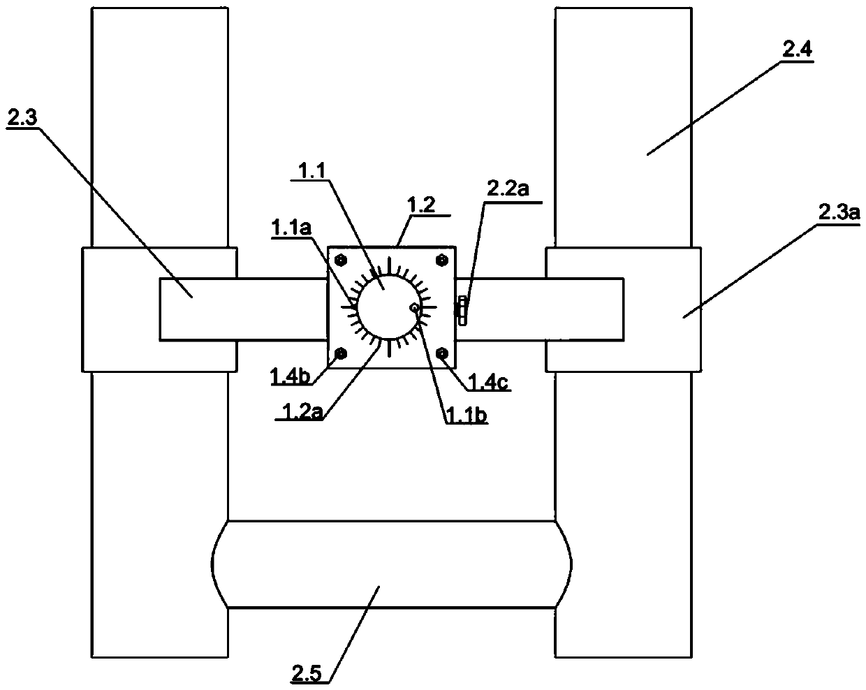
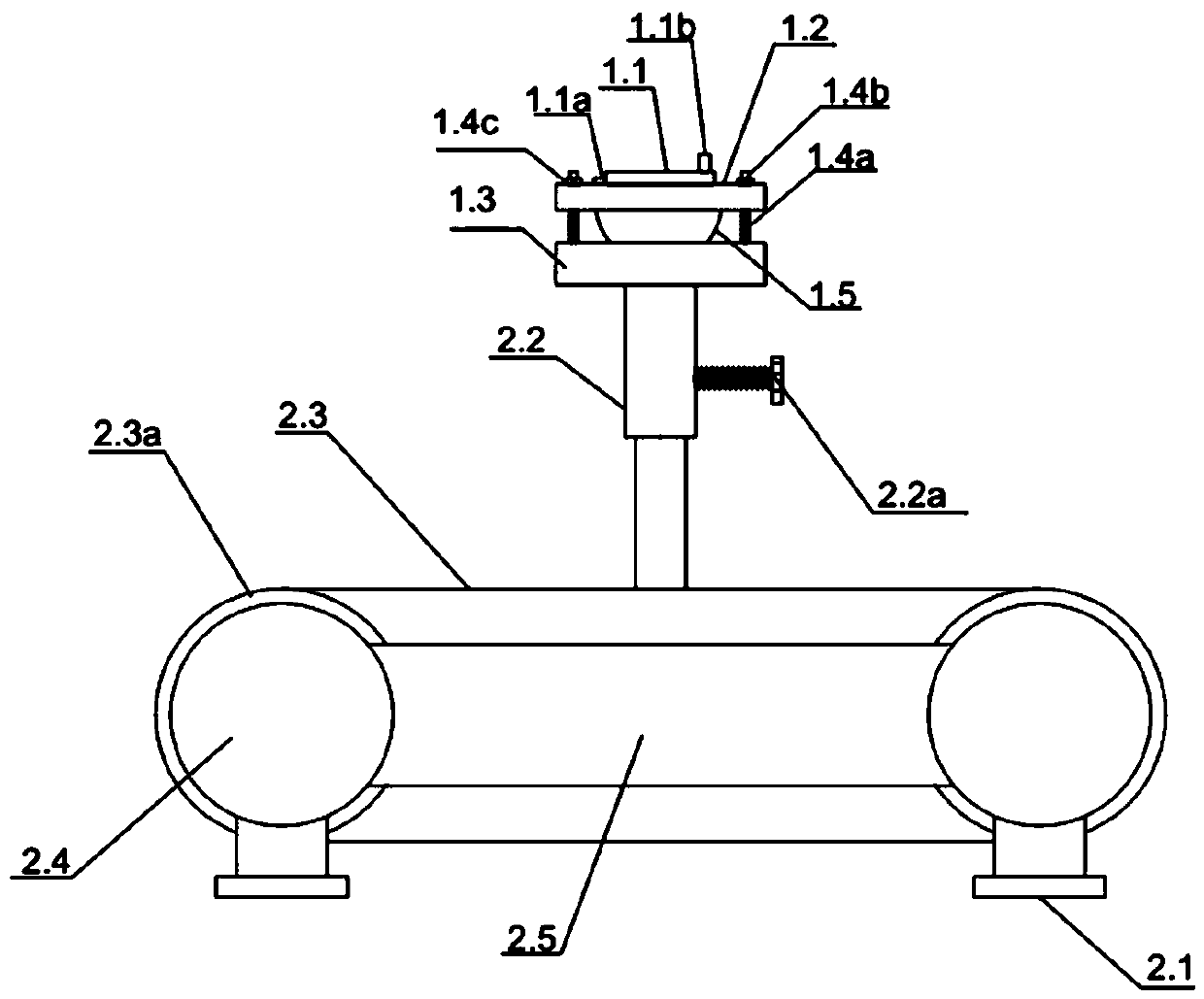
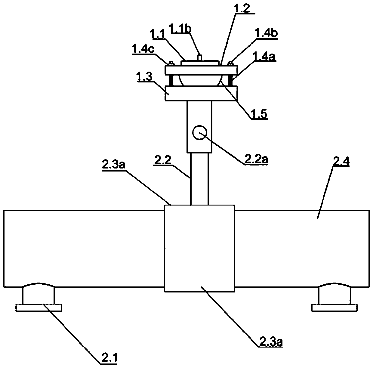
[0026] Such as Figure 1 to Figure 3 As shown, they are the top view, front view and right view of an X-ray residual stress detection sample stage provided in the specific embodiment of the present invention, the X-ray residual stress detection sample stage includes an object loading device with an adjustable rotation angle and a A position adjustment device for adjusting the position of the loading device; more specifically, such as Figure 4 and Figure 5 Shown are the front view and cross-sectional view of the loading device, respectively.

[0027] The loading device includes a loading platform 1.1, a positioning adjustment plate 1.2 and a base 1.3 arranged from top to bottom, the loading platform 1.1 is located on the positioning adjustment plate 1.2, and the lower surface of the loading platform 1.1 is provided with a rotating shaft 1.5a, and the positioning The central position of the adjustment plate 1.2 is provided with a rotating shaft through hole for the rotating ...

Embodiment 2

[0030] The technical content of this embodiment is basically the same as that of the first embodiment, except that in this embodiment, the bottom of the elevating rod 2.2 and the transverse connecting rod 2.3 are not fixedly connected, but slidingly connected. The specific way of the sliding connection is: the bottom of the elevating rod 2.2 is provided with a slider structure, and the upper surface of the transverse connecting rod 2.3 is provided with a horizontal through groove slidingly matched with the slider at the bottom of the elevating rod 2.2 along its axial direction, as shown in the figure The structure of the slider and the transverse channel is not shown.

[0031]When performing X-ray residual stress detection focusing on a small sample, first, place the workpiece on the stage 1.1; then, by manipulating the rotating handle 1.1b to drive and rotate the concave spherical body 1.5 to slide on the upper surface of the base 1.3, to Adjust the rotation angle of the work...


PUM


Abstract

The invention discloses an X-ray residual stress detection sample table, belongs to the technical field of residual stress detection, and aims to solve the technical problems of low focusing efficiency and long consumed time during a residual stress test carried out on a workpiece in multiple directions in the prior art. The sample table comprises an object carrying device and a position adjustingdevice connected to the bottom end of the object carrying device; the object carrying device comprises an object carrying table, a positioning adjusting plate, a rotary adjusting spherical body and abase which are sequentially arranged from top to bottom; the object carrying table is fixedly connected with the rotary adjusting spherical body through a rotary shaft; the rotating shaft penetratesthrough the positioning adjusting plate and is in sliding connection with the positioning adjusting plate in a radial direction; the top face of the base is provided with an inwards-recessed sphericalsurface matched with the rotary adjusting spherical body; the rotary adjusting spherical body is in sliding connection with the base through the inwards-recessed spherical surface; and a positioningmechanism is connected between the positioning adjusting plate and the base.

Description

technical field [0001] The invention relates to an X-ray residual stress detection sample stage, which belongs to the technical field of residual stress detection. Background technique [0002] X-ray is one of the few non-destructive testing methods in surface detection residual stress technology. It measures stress according to the crystal plane changes of materials or products. It is still the most widely studied, deep and mature internal stress measurement method and is widely used in science Various fields of research and industrial production. [0003] In order to comprehensively and accurately evaluate the residual stress, it is necessary to test the residual stress in all directions of the workpiece. The existing X-ray residual stress detector can only test the residual stress in one direction of the workpiece at a time. When changing to another direction, due to Compared with the change of the position during the previous test, it is easy to produce a large test err...

Claims


Application Information

Patent Timeline
IPC IPC(8): G01L5/00
CPCG01L5/0047
Inventor 赵佳佳云中煌刘小松
Owner NANJING ZHONGCHE PUZHEN URBAN RAIL VEHICLE CO LTD
Why Eureka
Try Eureka