[0047] The technical solutions in the embodiments of the present invention will be clearly and completely described below with reference to the accompanying drawings in the embodiments of the present invention. Obviously, the described embodiments are only a part of the embodiments of the present invention, but not all of the embodiments. Based on the embodiments of the present invention, all other embodiments obtained by those of ordinary skill in the art without creative efforts shall fall within the protection scope of the present invention.
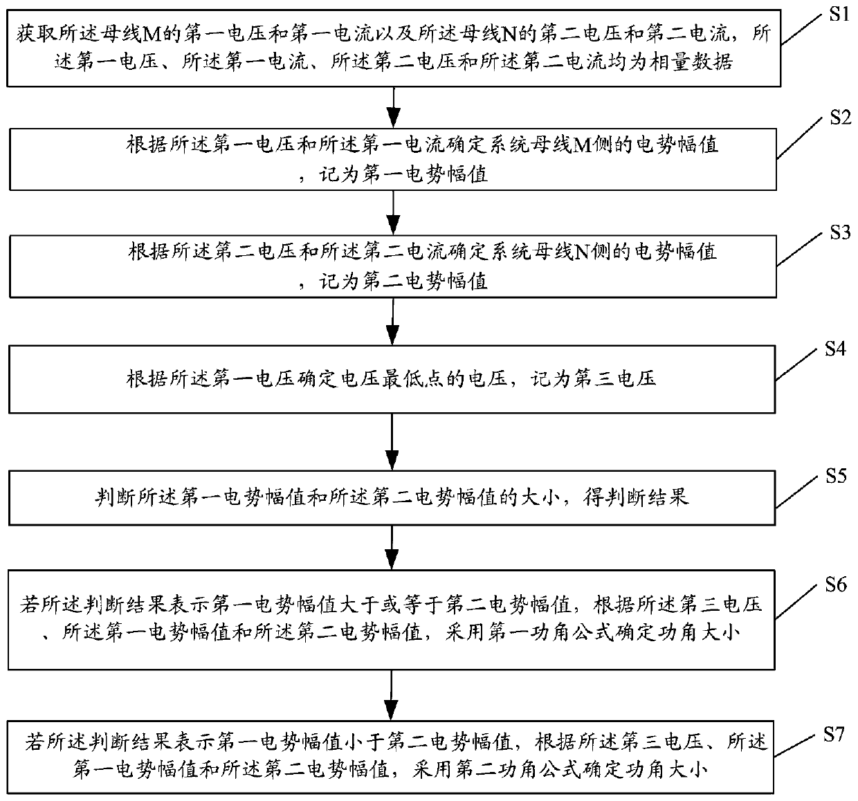
[0048] The purpose of the present invention is to provide a real-time determination method and system of the power angle to improve the accuracy of the power angle.
[0049] In order to make the above objects, features and advantages of the present invention more clearly understood, the present invention will be described in further detail below with reference to the accompanying drawings and specific embodiments.
[0050] The existing power angle measurement methods are based on the assumption that the potential amplitudes on both sides are equal, and the calculation error is large when the potential amplitudes on both sides are not equal.
[0051] figure 2 A schematic diagram of an equivalent dual power supply system according to an embodiment of the present invention, such as figure 2 As shown, the busbars M and N are equipped with phasor measurement PMU devices. The equivalent potential on both sides of the system is and The phase difference between the two is the power angle δ, that is The integrated impedance of the system is Z Σ =Z M +Z N +Z L , where ZM represents the equivalent impedance of the M-side system, Z N represents the equivalent impedance of the N-side system. Z L is the line impedance, and its impedance angle is
[0052] Assume that the equivalent potential amplitudes on both sides of the system are equal, and the impedance Z M ,Z N and Z L The impedance angles are equal, that is argZ M =argZ N =argZ L , then its phasor diagram is as follows image 3 shown.
[0053] After adopting the above classical assumptions, the lowest point of the voltage is located in the center of the integrated impedance of the system, and its voltage is U osc :
[0054]
[0055] Among them, U m is the measured M-side voltage of the PMU, for ahead of time Angle. The power system will usually item abbreviation
[0056] For a specific voltage class, E S , E W The fluctuations are not large and are approximately known parameters. Therefore, by image 3 can be obtained, the system power angle is
[0057]
[0058] The above is based on the current measurement of the power angle based on the equal potential amplitudes on both sides, but the calculation error is relatively large. Therefore, on this basis, the present invention proposes a real-time determination method for the power angle. If they are not equal, different power angle calculation schemes are used to determine the power angle. The following is the detailed flow of the present invention.
[0059] figure 1 It is a flowchart of a method for determining a power angle in real time according to an embodiment of the present invention, see figure 1 , a real-time determination method of power angle, suitable for an equivalent dual power supply system, the system is provided with a busbar M and a busbar N, and a phasor measurement device is provided at the busbar M and the busbar N, and the The phasor measuring device is used to measure the voltage and current of the bus, and the method for determining the power angle in real time includes the following steps:
[0060] S1: Acquire a first voltage and a first current of the bus bar M and a second voltage and a second current of the bus bar N, the first voltage, the first current, the second voltage and the first voltage Both currents are phasor data.
[0061] S2: Determine the potential amplitude on the M side of the system bus according to the first voltage and the first current, and record it as the first potential amplitude.
[0062] S3: Determine the potential amplitude on the N side of the system bus according to the second voltage and the second current, and record it as the second potential amplitude.
[0063] S4: Determine the voltage at the lowest point of the voltage according to the first voltage, which is recorded as the third voltage.
[0064] The determining of the voltage at the lowest point of the voltage according to the first voltage is specifically:
[0065] According to the formula Calculate the voltage at the lowest point of the voltage, where U m represents the magnitude of the first voltage, express ahead of time Angle, represents the first voltage, represents the first current, represents the impedance angle.
[0066] S5: Determine the magnitudes of the first potential amplitude and the second potential amplitude, and obtain a determination result.
[0067] S6: If the judgment result indicates that the first potential amplitude is greater than or equal to the second potential amplitude, use the first power angle according to the third voltage, the first potential amplitude and the second potential amplitude The formula determines the size of the power angle, and the magnitude of the potential represents the magnitude of the potential.
[0068] The first power angle formula is:
[0069]
[0070] Among them, U osc represents the voltage at the lowest point of the voltage, E S represents the first potential amplitude, E W represents the second potential amplitude, and O represents the lowest point of the voltage.
[0071] S7: If the judgment result indicates that the first potential amplitude is smaller than the second potential amplitude, use the second power angle formula to determine according to the third voltage, the first potential amplitude and the second potential amplitude Angle size.
[0072] The second power angle formula is:
[0073]
[0074] Among them, U osc represents the voltage at the lowest point of the voltage, E S It means that the first potential amplitude is E W It means that the second potential amplitude is O represents the lowest point of voltage.
[0075] Specifically, when the potential amplitudes on the two sides are not equal, considering the drift characteristics of the lowest point of the voltage, the power angle calculation method based on the electrical quantity on one side has a large error, especially when the power angle is small and the power angle increases to close to At 2π, the error is the largest. Aiming at the situation that the potential amplitudes on both sides are not equal, the invention proposes a power angle measurement scheme based on the electrical quantities on both sides, with high accuracy.
[0076] Figure 4 is the voltage phasor diagram when the potential amplitudes on both sides are not equal in the embodiment of the present invention, wherein Figure 4 Part (a) of , indicates that point O lies outside the potential line, where Figure 4 Part (b) of , indicates that point O is located within the potential line.
[0077] Assumption Potential amplitude ratio on both sides And assume that the potential amplitude E on both sides S , E W constant. The voltage phasor diagram of the power angle in the range of 0 to π, such as Figure 4 shown. Among them, the O point is the lowest point of the voltage, which corresponds to the voltage U osc by formula beg.
[0078] For the range of δ∈(0~π), when the power angle is small, the lowest point of the voltage is located outside the potential connection line on both sides, and when the power angle is large, the voltage lowest point is located within the potential connection line on both sides. The critical point of the two is δ=arccos(1/k). Similarly, when δ∈(π~2π), the critical point is δ=2π-arccos(1/k).
[0079] Therefore, the expression of the power angle δ is:
[0080]
[0081] when In the same way, the expression of the power angle δ can be obtained as:
[0082]
[0083] when When , the O point is always located within the potential connection line, and the formula can be arranged as time formula form.
[0084] In the end, there are two cases, and
[0085] The calculation of the system electromotive force:
[0086] The embodiment of the present invention divides the system equivalent potential amplitude E S , E W In addition, all other electrical quantities are known or can be obtained by measurement. Therefore, the calculation of the power angle lies in the calculation of E S , E W , the system potential Satisfy:
[0087]
[0088] in, represents the first voltage, represents the first current, represents the first voltage, Indicates the first current, measured by the PMU, the system impedance Z M and Z N When the system is short-circuited and not operating in all phases, it can be obtained from the principle of fault components:
[0089]
[0090] in, represents the voltage fault component at point M, represents the voltage fault component at point N, represents the current fault component at point M, Indicates the N-point current fault component.
[0091] E S , E W There are several solutions available:
[0092] 1) The equivalent potential amplitude is directly replaced by the steady-state voltage. In engineering, the system potential amplitude E after disturbance S , E W Often take the voltage value U of the busbars M and N in the steady state m0 , U n0 , namely E S =U m0 ,E W =U n0.
[0093] 2) Short circuit fault, when the system has a symmetrical fault in the positive direction,
[0094]
[0095] in, represents the positive sequence fault component of the voltage at point M, represents the positive sequence fault component of the voltage at point N, represents the positive sequence fault component of the current at point M, Indicates the positive sequence fault component of the N-point current.
[0096] When a positive-direction asymmetric fault occurs in the system, considering that the positive and negative sequence impedances of the system are approximately equal,
[0097]
[0098] in, represents the negative sequence fault component of the voltage at point M, represents the negative sequence fault component of the voltage at point N, represents the negative sequence fault component of the current at point M, Indicates the negative sequence fault component of the current at point N.
[0099] Find the system impedance Z M ,Z N after, according to Calculate the system potential E under different short-circuit faults for the measured value of the PMU after the fault is removed S , E W.
[0100] 3) Non-full phase operation, Figure 5 A diagram of an equivalent dual power supply system for non-all-phase operation according to the embodiment of the present invention, as shown in Figure 5 As shown, the voltage and current of busbars M and N are taken as:
[0101]
[0102] In the formula, It is the positive sequence voltage and positive sequence current of busbars M and N. Simultaneous formula, the system potential E can be obtained under the non-all-phase operating state S , E W.
[0103] E S , E W The search method is not limited to the above. get E S , E W After that, the power angles on both sides of the system after the disturbance can be measured in real time by substituting the formula of the first power angle or the second power angle.
[0104] Image 6 It is a schematic structural diagram of a real-time power angle determination system according to an embodiment of the present invention, see Image 6 , a real-time power angle determination system, suitable for an equivalent dual power supply system, the dual power supply system is provided with a busbar M and a busbar N, and a phasor measurement device is provided at the busbar M and the busbar N, The phasor measurement device is used to measure the voltage and current of the bus, and the real-time power angle determination system includes:
[0105] A voltage and current acquisition module 601, configured to acquire a first voltage and a first current of the bus bar M and a second voltage and a second current of the bus bar N, the first voltage, the first current, the Both the second voltage and the second current are phasor data;
[0106] a first potential determination module 602, configured to determine the potential amplitude on the M side of the system bus according to the first voltage and the first current, which is recorded as the first potential amplitude;
[0107] A second potential determining module 603, configured to determine the potential amplitude on the N side of the system bus according to the second voltage and the second current, which is recorded as the second potential amplitude;
[0108] A third voltage determination module 604, configured to determine the voltage at the lowest point of the voltage according to the first voltage, which is denoted as the third voltage;
[0109] Judging module 605, for judging the magnitude of the first potential amplitude and the second potential amplitude, and obtaining a judgment result;
[0110] The power angle determination module 1 606 is configured to, if the judgment result indicates that the first potential amplitude is greater than or equal to the second potential amplitude, according to the third voltage, the first potential amplitude and the second potential amplitude value, use the first power angle formula to determine the size of the power angle;
[0111] The second power angle determination module 607 is configured to, if the judgment result indicates that the first potential amplitude is smaller than the second potential amplitude, according to the third voltage, the first potential amplitude and the second potential amplitude, Use the second power angle formula to determine the size of the power angle.
[0112] Preferably, the first power angle formula is:
[0113]
[0114] Among them, U osc represents the voltage at the lowest point of the voltage, E S represents the first potential amplitude, E W represents the second potential amplitude, and O represents the lowest point of the voltage.
[0115] Preferably, the second power angle formula is:
[0116]
[0117] Among them, U osc represents the voltage at the lowest point of the voltage, E S represents the first potential amplitude, E W represents the second potential amplitude, and O represents the lowest point of the voltage.
[0118] The third voltage determination module is specifically:
[0119] a third voltage determination unit for determining according to the formula Calculate the voltage at the lowest point of the voltage, where U m represents the magnitude of the first voltage, express ahead of time Angle, represents the first voltage, represents the first current, express.
[0120] The present invention uses the electric potential on both sides to determine the power angle, and has higher accuracy than the traditional measurement method based on the electric potential on one side.
[0121] In the present invention, when the potentials on both sides are not equal, the magnitude of the potential amplitudes on both sides and After classification and discussion, the calculation formula of power angle in different situations is finally given, and the measurement accuracy of power angle is greatly improved by this method.
[0122] The invention is suitable for the determination of the power angle of the interconnected system. In the case that the potentials on both sides of the system are not equal, for the two situations where the voltage lowest point is located inside and outside the potential connection line on both sides, by calculating the voltage at the lowest point and the potential amplitude of the system on both sides value to obtain the power angle calculation scheme under different conditions. Contrast with tradition For the power angle measurement method, when the lowest point of the voltage is outside the potential connection line on both sides, a power angle calculation formula suitable for this situation is given, and the measurement accuracy is high.
[0123] The power angle determination method and system proposed by the present invention can be applied to monitor and improve the stability of the power system. When the power system is impacted by disturbance, the power angle between the potentials on both sides increases gradually. By applying the method for determining the power angle of the present invention, the power angle can be measured in real time and the stability of the system can be judged. When δ>90°, it is judged that the system is statically unstable; when δ>180°, it is judged that the system is transiently unstable.
[0124] In addition, the power angle calculation formula can be applied to the power system stability control, that is, if it is detected that the system is about to become unstable through the power angle measurement, it can be matched with the stability control measures. For example, the commutation sequence control measures, real-time measurement of the power angle, detection of the power angle swing to the preset power angle value, and the commutation sequence operation. And after the commutation sequence (the system power angle is reduced by 120°), the change of the system power angle and the stability of the system are monitored in real time.
[0125] The invention is also applicable to other stable control measures such as fast phase shift control of the phase shifter, control of changing the wiring mode of the secondary winding of the transformer, and the like.
[0126] It can also be used for distance protection oscillation blocking:
[0127] When the system oscillates, the method of the present invention is used to monitor the size of the power angle in real time. If the power angle is small, δ<80°, the distance protection is allowed to open, so that when a fault occurs in the area, the distance element can move quickly; if the power angle is large, δ >80°, the oscillation and short-circuit fault should be judged. If it is judged to be oscillation, the distance protection will be blocked to prevent the oscillation malfunction.
[0128] For a system with unequal potential amplitudes on both sides, the traditional formula-based power angle calculation method may cause the calculated power angle to be greater than 80° when the actual power angle is small, and the distance protection will be blocked incorrectly. The method of the present invention can effectively avoid this situation.
[0129] The method of the present invention can be applied to power system measurement, out-of-step decoupling, oscillation monitoring and the like.
[0130] The various embodiments in this specification are described in a progressive manner, and each embodiment focuses on the differences from other embodiments, and the same and similar parts between the various embodiments can be referred to each other. For the system disclosed in the embodiment, since it corresponds to the method disclosed in the embodiment, the description is relatively simple, and the relevant part can be referred to the description of the method.
[0131] The principles and implementations of the present invention are described herein using specific examples. The descriptions of the above embodiments are only used to help understand the method and the core idea of the present invention; meanwhile, for those skilled in the art, according to the present invention There will be changes in the specific implementation and application scope. In conclusion, the contents of this specification should not be construed as limiting the present invention.