
Automatic debugging device for filter

An automatic debugging and filter technology, which is applied to waveguide devices, electrical components, circuits, etc., can solve problems such as low efficiency, and achieve the effects of improving efficiency, avoiding mixing, and saving space

Inactive Publication Date: 2019-12-31
WUHAN XINHAO INTELLIGENT TECH CO LTD
View PDF0 Cites 3 Cited by
  • Summary
  • Abstract
  • Description
  • Claims
  • Application Information

AI Technical Summary

Problems solved by technology

[0004] The purpose of the present invention is to provide an automatic filter debugging device, which is used to solve the problem that the debugging of the filter signal frequency in the industry is basically manual debugging, and the efficiency is low

Method used


Image

  • Automatic debugging device for filter
  • Automatic debugging device for filter
  • Automatic debugging device for filter

Examples


Embodiment Construction

[0042]In order to better understand the present invention, the technical solutions of the present invention will be further described below in conjunction with the embodiments and the accompanying drawings.

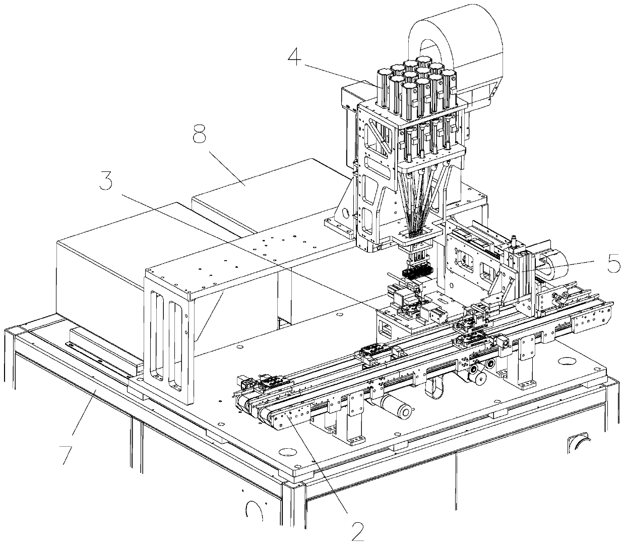
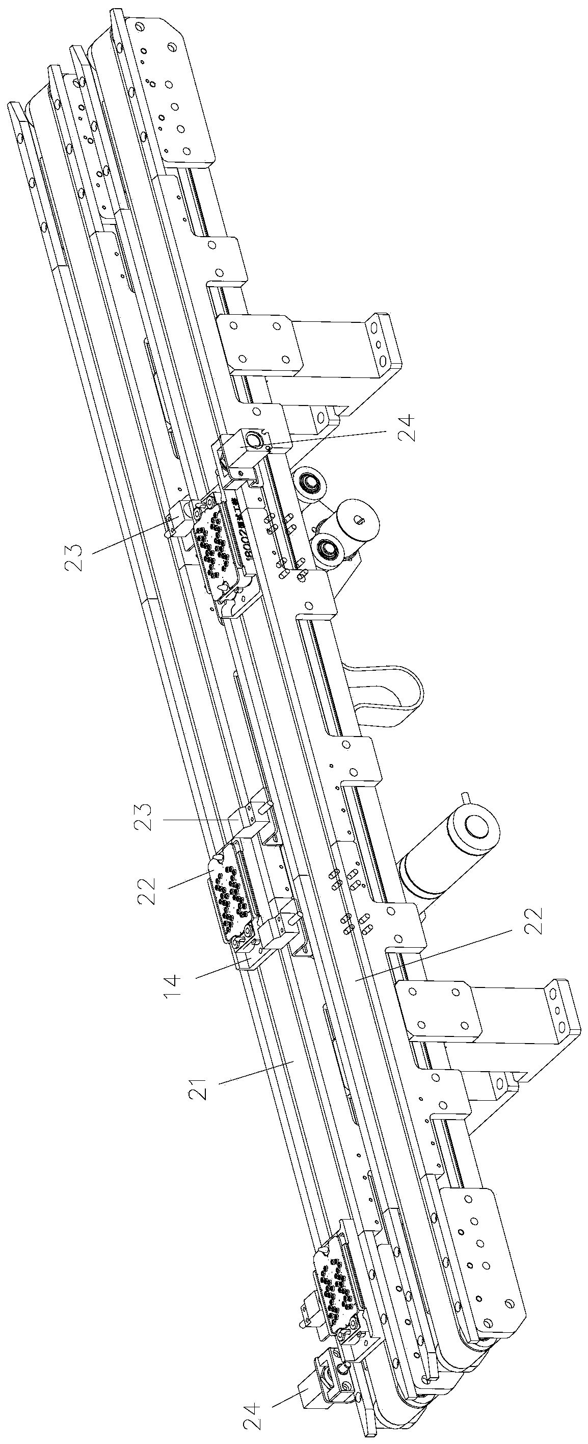
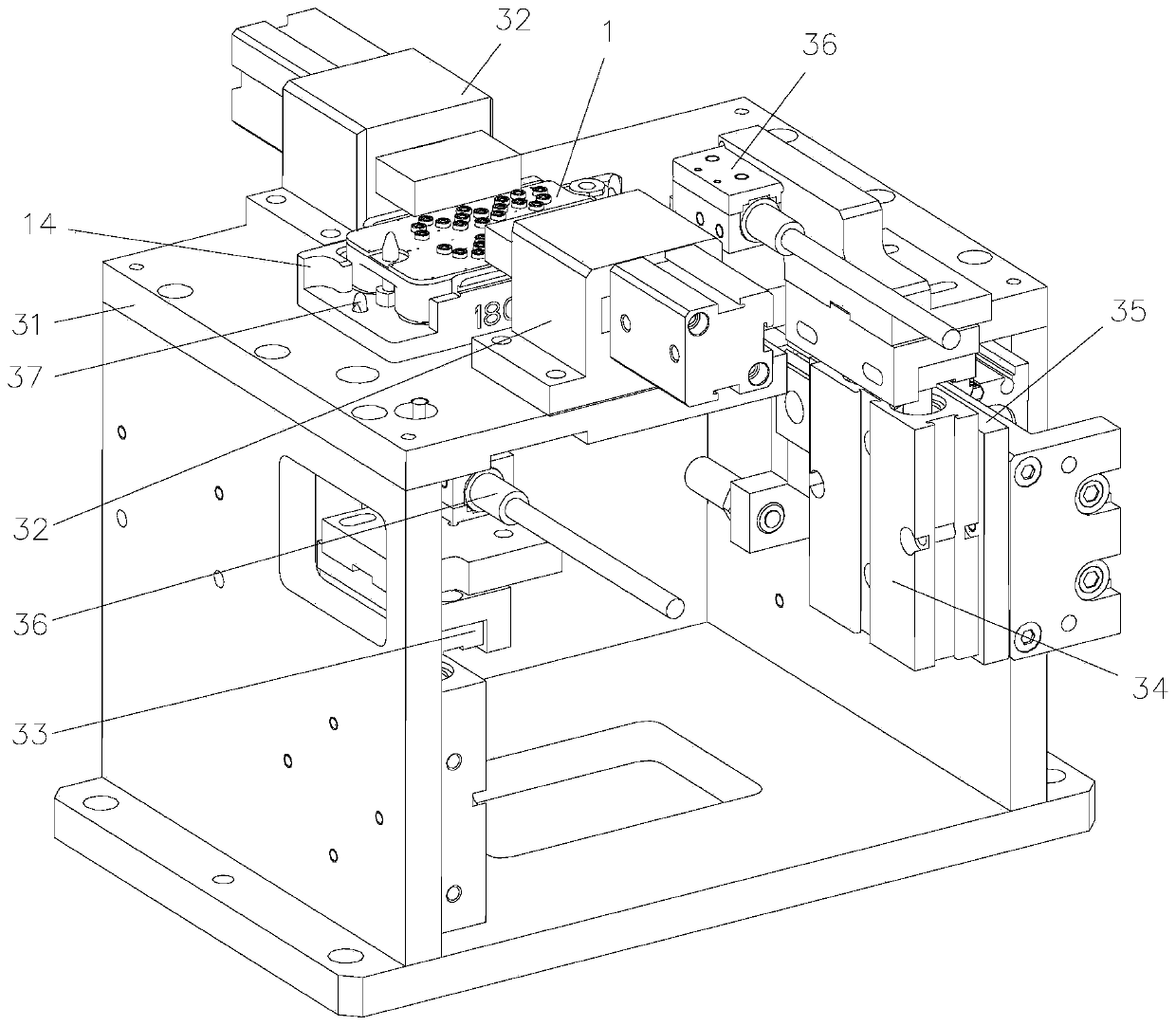
[0043] Such as Figure 1-9 As shown, the filter debugging device of a specific embodiment includes a filter transmission line 2 installed on a frame 7, a debugging workbench 3, a tuning screw debugging mechanism 4 and a transplanting manipulator 5, and the filter transmission line 2 is located at The front part of the frame 7, the debugging workbench 3 is located on one side of the filter conveying line 2; the debugging workbench 3 is equipped with a transplanting manipulator 5, and the transplanting manipulator 5 is used for The filter product 1 is transported between 2 and the debugging workbench 3; the debugging workbench 3 is also equipped with a tuning screw debugging mechanism 4, and the tuning screw debugging mechanism 4 is located above the debugging workbench 3, ...


PUM


Abstract

The invention belongs to the field of filter debugging, and particularly relates to an automatic debugging device for a filter, which comprises a filter conveying line, a debugging workbench, a tuningscrew debugging mechanism and a transplanting manipulator arranged on a rack, wherein the debugging workbench is located on one side of the filter conveying line and provided with the transplanting manipulator, and the transplanting manipulator is used for conveying filter products between the filter conveying line and the debugging workbench; the debugging workbench is further provided with thetuning screw debugging mechanism, and the tuning screw debugging mechanism is located above the debugging workbench and used for debugging a filter product located on the debugging workbench. The device provided by the invention is used for solving the problems that the debugging of the filter signal frequency in the current industry is basically manual debugging, and the efficiency is low; full-automatic debugging is achieved; and the production efficiency is improved.

Description

technical field [0001] The invention belongs to the field of filter debugging, and in particular relates to an automatic debugging device for a filter. Background technique [0002] Filters have played an important role in circuits since the beginning of the development of telecommunication, and have made continuous progress with the development of communication technology. In the field of modern communication technology, almost no branch is not affected by digital filtering technology. Digital filters are widely used in source coding, channel coding, modulation, multiplexing, data compression, and adaptive channel equalization, especially in applications such as digital communication, network communication, and image communication. , almost impossible to move. With the advent of the 5G era, the new communication system requires the development of a technology that can extract and detect signals in a specific frequency band, and the development of this technology has furth...

Claims


Application Information

Patent Timeline
Patent Type & Authority Applications(China)
IPC IPC(8): H01P11/00
CPCH01P11/007
Inventor 代杨帆屈红军李明杨涛曾旋焱曹首科邵露吴国彪柳其硕薛小鹏
Owner WUHAN XINHAO INTELLIGENT TECH CO LTD
Learn More