
Method for determining an offset of a rotor position sensor, control device for a converter, and electric machine for a vehicle

A rotor position and control device technology, which is applied to devices using electric/magnetic methods, control generators, control electromechanical transmissions, etc., can solve problems such as offset, reduce component costs, and eliminate voltage measurement.

Pending Publication Date: 2019-12-31
VALEO EAUTOMOTIVE GERMANY GMBH
View PDF1 Cites 0 Cited by
  • Summary
  • Abstract
  • Description
  • Claims
  • Application Information

AI Technical Summary

Problems solved by technology

However, when assembling the rotor position sensor there is an offset, that is, an offset between its zero axis and the magnetic d axis

Method used


Image

  • Method for determining an offset of a rotor position sensor, control device for a converter, and electric machine for a vehicle
  • Method for determining an offset of a rotor position sensor, control device for a converter, and electric machine for a vehicle

Examples


Embodiment Construction

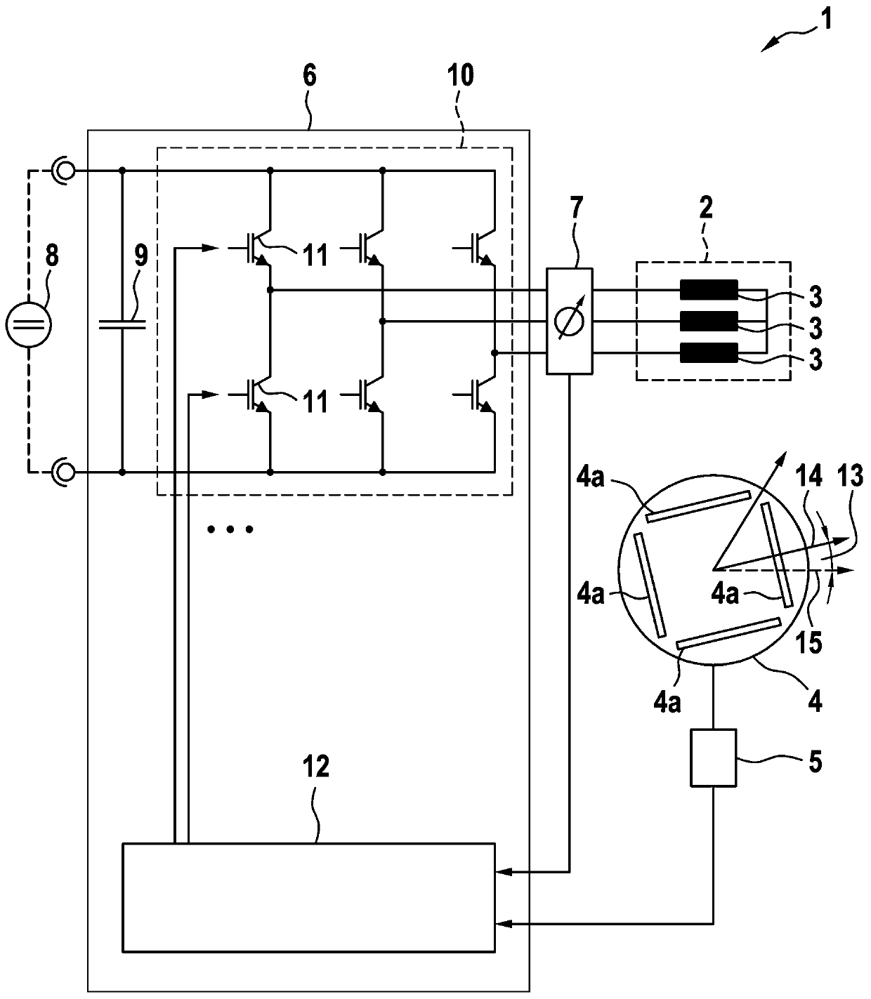
[0030] figure 1 is a schematic diagram of an embodiment of an electrical machine 1 comprising a stator 2 with a stator winding 3 , a rotor 4 , a rotor position sensor 5 arranged at the rotor and an inverter 6 arranged for the stator winding 3 Supply polyphase AC voltage. The rotor has a plurality of permanent magnets 4a or is externally excited. Furthermore, the electric machine 1 has a current measuring device 7 which detects the phase currents in the stator winding 3 . The electric machine 1 is used as the drive machine of an electric or hybrid vehicle with a high-voltage battery 8 , which supplies an inverter 6 on the input side.

[0031] On the input side, the converter 6 comprises an intermediate circuit capacitor 9 and a power unit 10 with a plurality of switching elements 11 connected to form half bridges, the respective half bridges supplying the phases of the stator 2 . Furthermore, the converter 6 has a control device 12 which actuates the switching element 11 in ...


PUM


Abstract

The invention relates to a method for determining an offset (13) of a rotor position sensor (5), which is arranged on a rotor (4) of an electric machine (1). The method comprises the following steps:determining a first value of a rotor position by means of an electromotive force induced by the rotor (4) in a stator winding (3) of a stator (2) of the electric machine (1) at a predetermined rotational speed; determining a second value of the rotor position by means of a magnetic anisotropy of the electric machine (1) depending on the rotor position; verifying one of said values by means of theother value; and determining an offset (13) of the rotor position sensor (5) depending on the verified value and a third value of the rotor position derived from rotor position information of the rotor position sensor (5).

Description

technical field [0001] The invention relates to a method for determining an offset of a rotor position sensor. Furthermore, the invention relates to a control device for an inverter and an electric machine for a vehicle. Background technique [0002] Motors are often adjusted by means of a magnetic d-axis, which describes the rotor position, wherein the rotor position is often provided by a rotor position sensor, for example a resolver, during operation of the motor. However, when assembling the rotor position sensor there is an offset, ie an offset between its zero axis and the magnetic d-axis. In order to take the offset into account when regulating the electric machine, it can be determined by means of the electromotive force induced by the rotor in the stator winding of the stator of the electric machine at a predetermined rotational speed. [0003] For example, the document DE 10 2011 090 127 A1 discloses a hybrid control method in which a candidate offset value of th...

Claims


Application Information

Patent Timeline
Patent Type & Authority Applications(China)
IPC IPC(8): H02P6/182B60L15/20H02P21/18G01P3/46
CPCH02P6/182B60L15/20H02P21/18G01P3/46B60L3/0038H02P6/183H02P2203/05Y02T10/64Y02T10/72
Inventor K·维德曼
Owner VALEO EAUTOMOTIVE GERMANY GMBH
Learn More