Handheld dust collector separation method for separating dust cup assembly by one key

A separation method and vacuum cleaner technology, which is applied in the direction of vacuum cleaners, suction filters, cleaning equipment, etc., can solve the problems of shaking dust cups, easy gaps at joints, and affecting the firmness of dust cup components, so as to achieve convenient disassembly and high efficiency. Effect

Pending Publication Date: 2020-01-03
苏州意达产品设计有限公司
View PDF6 Cites 6 Cited by
  • Summary
  • Abstract
  • Description
  • Claims
  • Application Information

AI Technical Summary

Problems solved by technology

The main problem of the existing connection methods between these dust cup assemblies and the main unit is that the connection between the main unit and the dust cup is prone to produce gaps, and the dust cup is likely to shake due to the drive of the motor in the main unit when the gap is in use. , will affect the firmness of the dust cup assembly fixed on the host

Method used


Image

  • Handheld dust collector separation method for separating dust cup assembly by one key
  • Handheld dust collector separation method for separating dust cup assembly by one key
  • Handheld dust collector separation method for separating dust cup assembly by one key

Examples


Embodiment 1

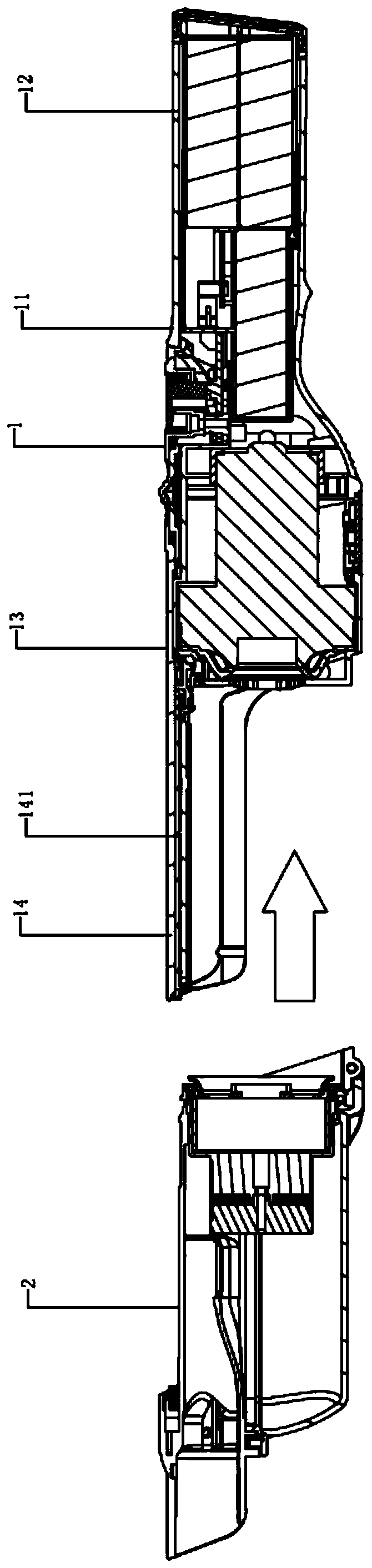
[0031] see Figure 1 to Figure 5 , the figure shows a hand-held vacuum cleaner with one-button separation of the dust cup assembly provided by the embodiment of the present invention, which includes a vacuum cleaner main body 1 and a dust cup assembly 2, and the first end 11 of the vacuum cleaner main body 1 extends outward to form a grip handle 12. The opposite second end 13 extends outward to form a dust cup connecting portion 14, which extends outward along the axial direction of the vacuum cleaner main body 1, and has a first slide rail 141 on the dust cup connecting portion 14, the first The slide rail 141 is arranged along the length direction of the dust cup connecting portion 14, and the second slide rail 21 is arranged on the dust cup assembly 2, and the second slide rail 21 is arranged along the axial direction of the dust cup assembly 2. The second slide rail 21 is inserted into the first slide rail 141 along the length direction of the first slide rail 141 , or the...

Embodiment 2

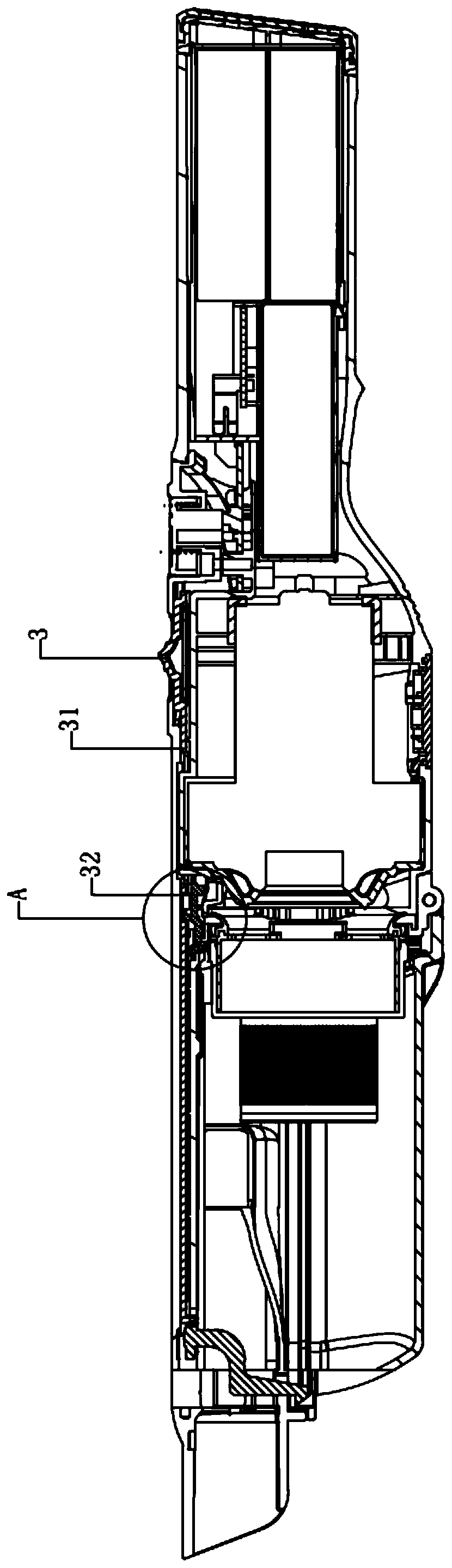
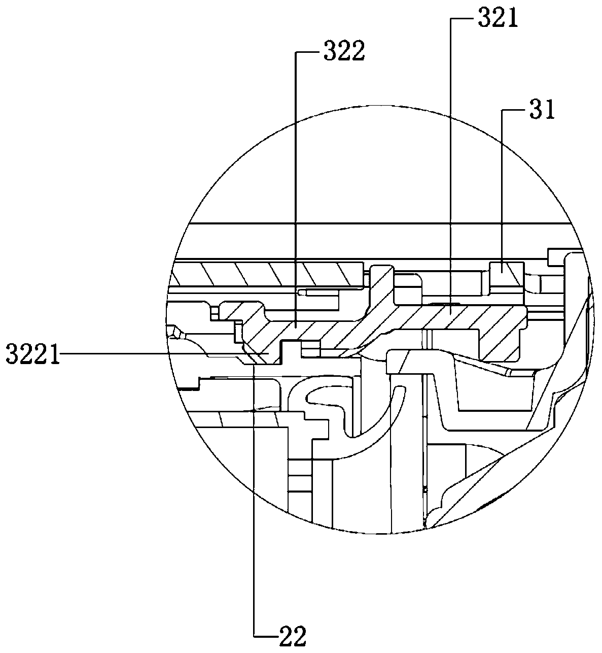
[0038] see Figure 1 to Figure 5 , the figure shows a hand-held vacuum cleaner with one-button separation of the dust cup assembly provided by Embodiment 3 of the present invention. On the basis of the above embodiments, this embodiment further makes the following technical solutions as improvements: the locking hook 32 has a driven end 321 and a hook end 322, which are integrally formed between the driven end 321 and the hook end 322, the end of the driving rod 31 pushes or pulls the driven end 321, and the hook end 322 hooks the clamping part 22; specifically , the cross-section of the driven end 321 is L-shaped, the cross-section of the hook end 322 is U-shaped, and the bottom has a hook body 3221 . Through the arrangement of the above structure, it can be ensured that the lock hook is firmly hooked to the dust cup assembly, and the decoupling of the lock hook is facilitated.

Embodiment 3

[0040] see Figure 1 to Figure 5 , the figure shows a hand-held vacuum cleaner with one-button separation of the dust cup assembly provided by Embodiment 3 of the present invention. On the basis of the above embodiment, this embodiment further makes the following technical solutions as improvements: dust cup The assembly 2 includes a dust cup 23 and an air duct 24, and the filter member 25 is detachably inserted into the dust cup 23 from an assembly hole provided on the inner end of the dust cup 23, and the dust cup 23 includes any plane in the height direction of the dust cup 23 The cup body 231 and the cup cover 232 as the dividing surface, the cup body 231 covers at least two sides of the dust cup 23, the cup cover 232 covers at least two sides of the dust cup 23, and the air duct 24 is integrated on the outer end of the cup body 231 , and the air inlet 241 of the air duct 24 extends outward from the outer end of the cup body 231 , and the air outlet 242 of the air duct 24 ...


PUM


Abstract

The invention provides a handheld dust collector separation method for separating a dust cup assembly by one key. A dust collector host and the dust cup assembly are included; the second end of the dust collector host outwards extends to form a dust cup connecting part; a first slide rail is arranged on the dust cup connecting part; the first slide rail is arranged in the length direction of the dust cup connecting part; a second slide rail is arranged on the dust cup assembly; the second slide rail arranged on the dust cup assembly is inserted into the first slide rail in the length directionof the first slide rail; a pulling button part is arranged on the surface of the dust collector host; the bottom of the pulling button part is connected with a driving rod; the end part of the driving rod pushes or pulls a lock hook; the lock hook is pushed or pulled by the end part of the driving rod to be unlocked; and the lock hook hooks a clamp connection part arranged on the dust cup assembly. Compared with the prior art, the method has the advantages that the hands cannot be dirty during dust cup cleaning or replacement, so that the dust cup can be more conveniently dismounted from thehost; and the dust cup replacing efficiency is higher.

Description

technical field [0001] The invention relates to the field of hand-held vacuum cleaners, in particular to a hand-held vacuum cleaner separation method for separating a dust cup assembly with one key. Background technique [0002] The handheld vacuum cleaner is a new type of vacuum cleaner at present. It has the characteristics of small size, easy to carry and use as a whole. It is a vacuum cleaner product between ordinary household vacuum cleaners and portable vacuum cleaners. Hand-held vacuum cleaners are more suitable for cleaning smaller spaces, such as cleaning inside a car, a small space in a home, or cleaning the workbench area in an office. [0003] In the current hand-held vacuum cleaner, its main components include the main engine and the dust cup assembly. For example, a Chinese patent discloses a hand-held surface cleaning device. image 3 The display, the dust cup assembly on it is integrated on the host; and in some existing hand-held vacuum cleaners, the dust cu...

Claims


Application Information

Patent Timeline
Patent Type & Authority Applications(China)
IPC IPC(8): A47L5/24A47L9/10
CPCA47L5/24A47L9/10
Inventor 李意
Owner 苏州意达产品设计有限公司
Why Eureka
Try Eureka