Motor electric engineering automatic welding machine

An automatic welding machine and electrical engineering technology, applied in the direction of welding equipment, auxiliary welding equipment, welding/cutting auxiliary equipment, etc., can solve the problems of unsafe use, weak welding, welding points in other positions, etc., and achieve easy movement Effect

Active Publication Date: 2020-01-03
SHANGQIU INST OF TECH
View PDF6 Cites 1 Cited by
  • Summary
  • Abstract
  • Description
  • Claims
  • Application Information

AI Technical Summary

Problems solved by technology

There are also some welding machines that can realize automatic welding, but they all weld along the set straight line, so the two steel plates must be placed in a specific position, otherwise it is very easy to weld the welding point in other positions during welding, resulting in Welding is not firm, and at the same time, some steel plates may have some gaps in themselves, so it is necessary to fill these gaps by welding, otherwise, there will be unsafe phenomena in use due to lack of welding. At the same time, when welding When the steel plate is placed on the base of the welding machine, because the steel plate is too thick, it is very laborious to move the steel plate on the base and move it on the base

Method used


Image

  • Motor electric engineering automatic welding machine
  • Motor electric engineering automatic welding machine
  • Motor electric engineering automatic welding machine

Examples


Embodiment 1

[0021] This embodiment provides an automatic welding machine for electrical engineering, and realizes the present invention through the basic necessary technical features to solve the problems raised in the technical background section of this application document

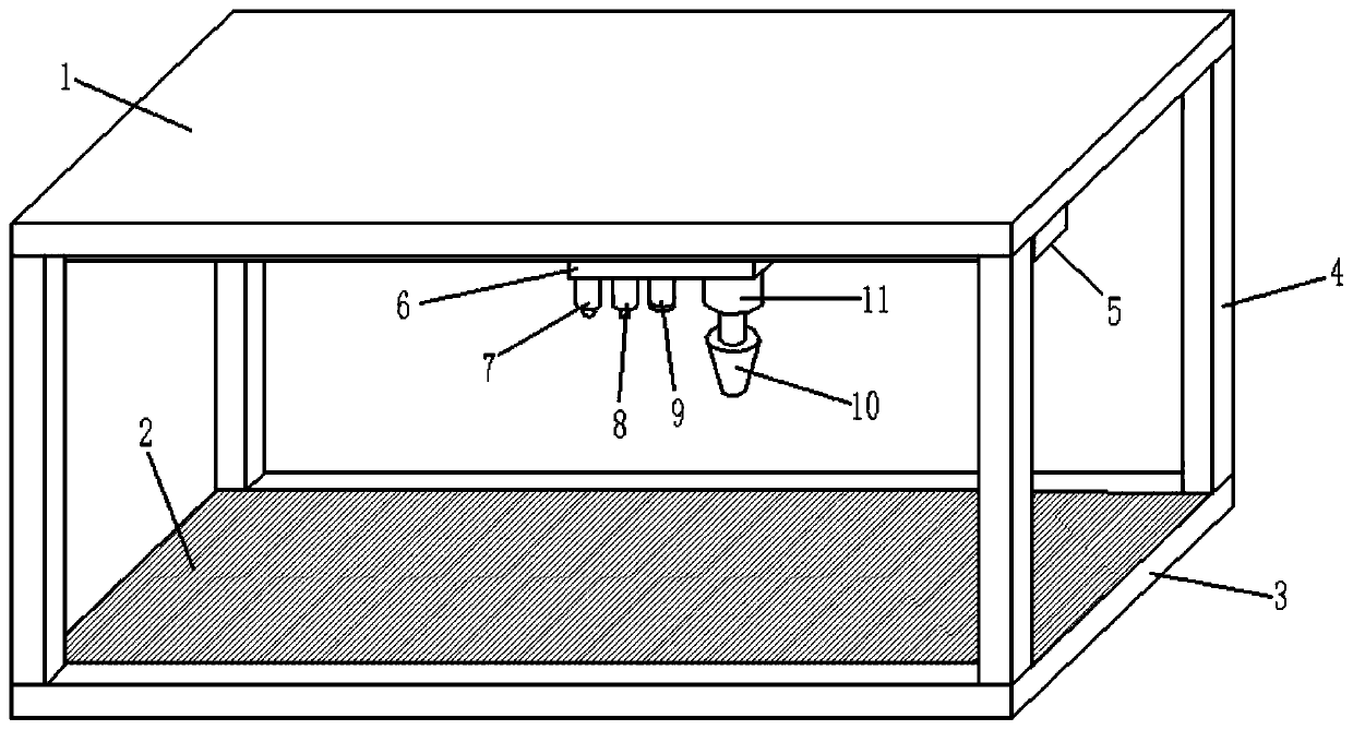
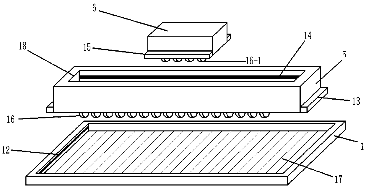
[0022] Specifically, such as Figure 1-2 The illustrated embodiment of the present invention provides an automatic welding machine for electrical engineering, including a base 3, a support rod 3 is fixed on the base 3, a support plate 1 is fixed on the top of the support rod 3, and a support plate 1 is opened on the lower surface of the support plate 1. There is an upper groove 17, and an upper chute 12 is respectively provided on the groove wall on the left and right sides of the upper groove 17 along the horizontal direction. A vertical slide bar 5 is connected between them, and the longitudinal slide bar 5 is provided with a driving device 16 for driving the longitudinal slide bar 5 to slide back and forth. The ...

Embodiment 2

[0029] This example is based on Example 1 and optimizes the implementation in Example 1, so that this example is more stable and has better performance during operation, but it is not limited to the one described in this example implementation.

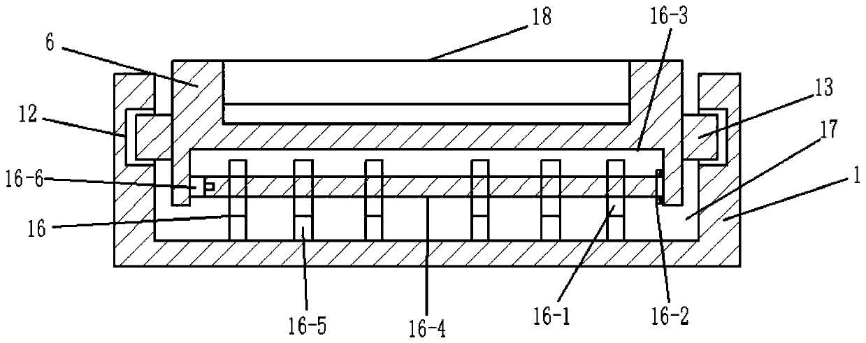
[0030] Specifically, such as image 3As shown, the driving device 16 on the horizontal slider 6 includes a driving groove 16-3 opened on the upper surface of the horizontal slider 6, and a motor 16-3 is fixed on the left side of the driving groove 16-3. 6. The output shaft of the motor 16-6 is fixedly connected to one end of the rotating shaft 16-4, and the other end of the rotating shaft 16-4 is connected to the groove wall on the right side of the driving groove 16-3 through the bearing 16-2, so The surface of the rotating shaft 16-4 is connected with a gear 16-1 through a key, and the gear 16-1 meshes with the rack 16-5, and the rack 16-5 is fixed on the groove bottom surface of the lower groove 18, and the control unit The signa...


PUM


Abstract

The invention discloses a motor electric engineering automatic welding machine. The motor electric engineering automatic welding machine comprises a base, wherein a supporting rod is fixed on the base; a supporting plate is fixed at the top of the supporting rod; an upper groove is formed in the supporting plate; an upper sliding groove is formed in the upper groove; an upper sliding block is connected to the upper sliding groove in a sliding manner; a longitudinal sliding strip is provided with a driving device and a lower groove; a lower sliding groove is formed in the lower groove; a lowersliding block is connected to the lower sliding groove in a sliding manner; a driving device is arranged on a transverse sliding block; a camera device, an infrared detection device, a light supplementing device and a lifting device are arranged on the lower surface of the transverse sliding block; and a welding device is arranged below the lifting device. According to the motor electric engineering automatic welding machine, the position of a gap is automatically identified, and then the gap is welded; not only can a steel plate to be welded be placed at will during welding, but also the gapon the surface of the steel plate can be welded, so that the unsafe phenomenon caused by the gap of the welded steel plate in the using process is avoided.

Description

technical field [0001] The invention relates to the technical field of automatic welding, in particular to an automatic welding machine for electrical engineering. Background technique [0002] When welding steel plates, usually the two steel plates to be welded are put together, and then welded using welding techniques, usually manually. There are also some welding machines that can realize automatic welding, but they all weld along the set straight line, so the two steel plates must be placed in a specific position, otherwise it is very easy to weld the welding point in other positions during welding, resulting in Welding is not firm, and at the same time, some steel plates may have some gaps in themselves, so it is necessary to fill these gaps by welding, otherwise, there will be unsafe phenomena in use due to lack of welding. At the same time, when welding When the steel plate is placed on the base of the welding machine, because the steel plate is too thick, it is very...

Claims


Application Information

Patent Timeline
Patent Type & Authority Applications(China)
IPC IPC(8): B23K37/00B23K37/02
CPCB23K37/00B23K37/0252
Inventor 杨晓东葛卫京黄胜银李国玄
Owner SHANGQIU INST OF TECH
Why Eureka
Try Eureka