Leather dust collecting and compressing device

A technology of dust collection and compression device, which is applied in the mechanical treatment of leather surface, raw hide/leather/fur manufacturing equipment, small raw hide/large raw hide/leather/fur processing, etc. , The effect of good use and simple structure

Pending Publication Date: 2020-01-03
QINGYUAN TENGXIANG LEATHER CO LTD
0 Cites 1 Cited by

AI-Extracted Technical Summary

Problems solved by technology

[0002] In the process of leather processing, the reverse side of the leather needs to be polished by a leather grinder. During this process, a lot of dust will be generated. The dust from the grindin...

Method used

Based on the leather dust collection compression device of above-mentioned technical feature, by connecting the dust pipe 4 at the exhaust port of the leather grinding machine, the dust pipe 4 is connected with the filter device 2, and fan 1 is set on the dust pipe 4 simultaneously, and the grinding The dust discharged from the leather machine is conveyed by the fan 1 to the filter device 2 for filtering, and the removed dust enters the dust compressor 3 for compression, and reaches a combustible compressed state for use as fuel, realizing waste utilization. At the same time, the filtered air is discharged from the air outlet 21 . The invention has the advantages of simple structure, good use effect and easy popularization and use.
In the present embodiment, described dust compressor 3 comprises frame 31, compression box 32, feed pipe 33, and described compression box 32 is arranged on the upper end of described frame 31, and the upper end of described compression box 32 A first oil cylinder 34 is provided, a compression plate 35 is arranged on the cylinder rod of the first oil cylinder 34, a second oil cylinder 36 and a third oil cylinder 37 are respectively arranged on the adjacent two sides of the compression box 32, and the second oil cylinder 36 The oil cylinder rods of the oil cylinder 36 and the third oil cylinder 37 are respectively provided with a first push plate 38 and a second push plate 39, and the side opposite to the third oil cylinder 37 of the compression box 32 is provided with a discharge port 3a, so that One end of the feed pipe 33 communicates with the compression tank 32 , and the other end is connected with the filter device 2 . By setting the first oil cylinder 34 on the upper end of the compression box 32 and the second oil cylinder 36 and the third oil cylinder 37 on the adjacent two sides, after the dust enters the compression box 32, the first oil cylinder 34 moves from top to bottom Compress the dust for the first time, then the second oil cylinder 36 pushes the dust and compresses it for the second time, and finally the third oil cylinder 37 compresses the...

Abstract

The invention relates to the technical field of leather processing, and discloses a leather dust collecting and compressing device. The leather dust collecting and compressing device comprises a fan,a filtering device, a dust compressor and a dust conveying pipe, wherein the dust conveying pipe is used for being connected with a leather grinder and is connected with the filtering device, the fanis arranged on the dust conveying pipe, the filtering device communicates with the dust compressor, and an air outlet is arranged on the filtering device. According to the leather dust collecting andcompressing device provided by the invention, an exhaust port of the leather grinder is connected with the dust conveying pipe, the dust conveying pipe is connected with the filtering device, the fanis arranged on the dust conveying pipe, the dust discharged by the leather grinder is conveyed to the filtering device by the fan to be filtered, the removed dust enters the dust compressor to be compressed, the compressed dust can reach the compression state capable of being combusted to be used as fuel, and waste utilization is achieved. Meanwhile, the filtered air is discharged from the air outlet. The leather dust collecting and compressing device has simple structure, good use effect and easy popularization and use.

Application Domain

Dispersed particle filtrationSkins/hides/leather/fur manufacturing apparatus +1

Technology Topic

Mechanical engineeringEnvironmental engineering +1

Image

  • Leather dust collecting and compressing device
  • Leather dust collecting and compressing device
  • Leather dust collecting and compressing device

Examples

  • Experimental program(1)

Example Embodiment

[0018] The specific embodiments of the present invention will be described in further detail below in conjunction with the drawings and embodiments. The following examples are used to illustrate the present invention, but not to limit the scope of the present invention.
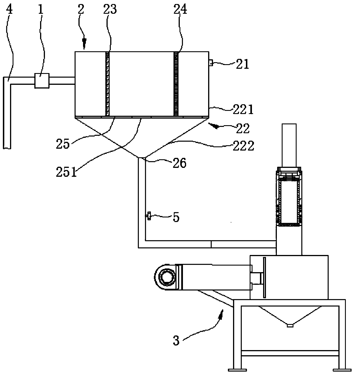
[0019] Such as figure 1 As shown, a leather dust collection and compression device according to a preferred embodiment of the present invention includes a fan 1, a filter device 2, a dust compressor 3, and a dust pipe 4 for connecting the exhaust port of the leather grinding machine. The dust pipe 4 is connected to the filter device 2, the fan 1 is arranged on the dust pipe 4, the filter device 2 is in communication with the dust compressor 3, and the filter device 2 is provided with an air outlet twenty one.
[0020] The leather dust collection and compression device based on the above technical features connects the dust pipe 4 to the exhaust port of the leather grinding machine, and the dust pipe 4 is connected to the filter device 2. At the same time, a fan 1 is installed on the dust pipe 4, and the leather grinding machine discharges The dust is transported by the fan 1 to the filter device 2 for filtering, and the removed dust enters the dust compressor 3 for compression, and reaches a combustible compression state for use as fuel, realizing waste utilization. At the same time, the filtered air is discharged from the air outlet 21. The invention has simple structure, good use effect, and is easy to popularize and use.
[0021] In this embodiment, the filter device 2 includes a housing 22 and a filter arranged inside the housing 22, the dust pipe 4 is passed through the housing 22, and the output end of the dust pipe 4 is located at Inside the housing 22, and the filter is arranged at the output end of the dust pipe 2. After the dust enters the housing 22, it is filtered by the filter, and the dust falls from the bottom of the housing 22 into the dust compressor 3 for compression, and the filtered air is discharged from the air outlet 21 to ensure The cleanliness of the exhaust gas. At the same time, in order to ensure the filtering effect, the filter includes a first filter screen 23 and a second filter screen 24 arranged in sequence along the dust movement direction. The second filter screen 24 has a smaller pore size than the first filter screen 23. , After the double filtering of the first filter 23 and the second filter 24, the filtering effect is ensured.
[0022] In addition, in order to ensure the installation of the filter and facilitate the filtered dust to fall to the dust compressor 3, a mounting plate 25 is provided inside the housing 22, and the mounting plate 25 divides the housing 22 Is an upper shell 221 and a lower shell 222, the mounting plate 25 is provided with a through hole 251 for dust to pass through, and the filter is arranged in the upper housing 221 and fixed on the mounting plate 25 . At the same time, the lower housing 222 has an inverted cone shape, and a discharge hole 26 is provided in the center of the lower housing 222. The discharge hole 26 is connected to the dust compressor 3 through a pipe. With valve 5. The dust collected by the filter falls from the through hole 251 to the lower housing 222. At the same time, the lower housing 222 is set in an inverted cone shape to facilitate dust falling into the discharge hole 26 to enter the dust compressor 3 for compression. By setting the valve 5, the communication or disconnection between the filter and the dust compressor 3 can be manually controlled according to needs.
[0023] In this embodiment, the dust compressor 3 includes a frame 31, a compression box 32, and a feed pipe 33. The compression box 32 is arranged at the upper end of the frame 31, and the upper end of the compression box 32 is provided with a An oil cylinder 34, a compression plate 35 is provided on the cylinder rod of the first oil cylinder 34, a second oil cylinder 36 and a third oil cylinder 37 are respectively provided on the adjacent two sides of the compression box 32, the second oil cylinder 36 and The cylinder rod of the third cylinder 37 is provided with a first push plate 38 and a second push plate 39 respectively. The compression box 32 is provided with a discharge port 3a on the side opposite to the third cylinder 37. One end of the tube 33 is connected with the compression box 32, and the other end is connected with the filter device 2. By arranging a first oil cylinder 34 at the upper end of the compression box 32 and a second oil cylinder 36 and a third oil cylinder 37 on the adjacent two sides, the first oil cylinder 34 moves from top to bottom after the dust enters the compression box 32 The dust is compressed for the first time, and then the second oil cylinder 36 pushes the dust and compresses it for the second time. Finally, the third oil cylinder 37 compresses the dust for the third time and pushes it to the discharge port 3a. The density of the material is high, and the volume of the material is small, forming a combustible compressed state to be used as fuel, realizing waste utilization.
[0024] In this embodiment, the bottom of the compression box 32 is provided with a scrap discharge port 3b. In the actual compression process, it is inevitable that some dust will not be compressed. By setting the scrap discharge port 3b, the uncompressed dust can be discharged in real time, avoiding the dust remaining in the compression box 32.
[0025] In this embodiment, the lower ends of the second cylinder 36 and the third cylinder 37 are each provided with a support rod 3c. One end of the two support rods 3c is connected to the frame 31, and the other end is respectively connected to the second The cylinder block of the cylinder 36 and the third cylinder 37. By providing the support rod 3c, the stability of the second cylinder 36 and the third cylinder 37 can be ensured, and the compression quality can be improved.

PUM

no PUM

Description & Claims & Application Information

We can also present the details of the Description, Claims and Application information to help users get a comprehensive understanding of the technical details of the patent, such as background art, summary of invention, brief description of drawings, description of embodiments, and other original content. On the other hand, users can also determine the specific scope of protection of the technology through the list of claims; as well as understand the changes in the life cycle of the technology with the presentation of the patent timeline. Login to view more.

Similar technology patents

Preparation method of high-specific-surface-area carbon molecular sieve for preparing nitrogen

ActiveCN106082172Alow costRealize waste utilization
Owner:宁夏天利丰能源利用有限公司

Continuous production process of cellulose sponge

ActiveCN112046043Areduce wasteRealize waste utilization
Owner:CHENGDU GRACE FIBER

Household garbage disposal machine

PendingCN110142282ASolve storage difficultiesRealize waste utilization
Owner:江苏建中环保科技有限公司

MgO-CaO-Fe2O3 series electric furnace ramming material prepared from fine magnesia-calcium brick powder

InactiveCN107266100ASimple preparation processRealize waste utilization
Owner:辽宁利尔镁质合成材料股份有限公司 +1

Method for calcining active lime

InactiveCN106380091AEfficient CalcinationRealize waste utilization
Owner:BO GUANG THERMAL ENERGY

Classification and recommendation of technical efficacy words

  • Realize waste utilization
  • Simple structure

MgO-CaO-Fe2O3 series electric furnace ramming material prepared from fine magnesia-calcium brick powder

InactiveCN107266100ASimple preparation processRealize waste utilization
Owner:辽宁利尔镁质合成材料股份有限公司 +1

Preparation method of high-specific-surface-area carbon molecular sieve for preparing nitrogen

ActiveCN106082172Alow costRealize waste utilization
Owner:宁夏天利丰能源利用有限公司

Household garbage disposal machine

PendingCN110142282ASolve storage difficultiesRealize waste utilization
Owner:江苏建中环保科技有限公司

Method for calcining active lime

InactiveCN106380091AEfficient CalcinationRealize waste utilization
Owner:BO GUANG THERMAL ENERGY

Continuous production process of cellulose sponge

ActiveCN112046043Areduce wasteRealize waste utilization
Owner:CHENGDU GRACE FIBER

Sharing system for air-conditioning coat

InactiveCN107440179ASimple structureeasy to wear
Owner:QINGDAO HAIER AIR CONDITIONER GENERAL CORP LTD

Feeding device of sorter of batteries plate

InactiveCN101357717ASimple structurecooperate well
Owner:NANJING NORMAL UNIVERSITY

Emergency parachuting device and method for multiple-rotor unmanned aerial vehicle

InactiveCN103895870Aavoid aircraft crashSimple structure
Owner:SOUTH CHINA AGRI UNIV +1
Why Eureka
Try Eureka