Protective bearing device with sliding blocks for eliminating clearance

A technology for protecting bearings and eliminating gaps, which is applied in the direction of bearing assembly, bearings, bearing components, etc., and can solve problems such as automatic protection of rotors

Active Publication Date: 2020-01-03
JIANGSU UNIV OF TECH
View PDF8 Cites 6 Cited by
  • Summary
  • Abstract
  • Description
  • Claims
  • Application Information

AI Technical Summary

Problems solved by technology

[0004] In order to solve the problem that the protection bearing device in the prior art cannot automatically protect the rotor in the event of a power failure, the present invention proposes a sliding block elimination gap protection bearing device, which solves the above technical problems

Method used


Image

  • Protective bearing device with sliding blocks for eliminating clearance
  • Protective bearing device with sliding blocks for eliminating clearance
  • Protective bearing device with sliding blocks for eliminating clearance

Examples


Embodiment 1

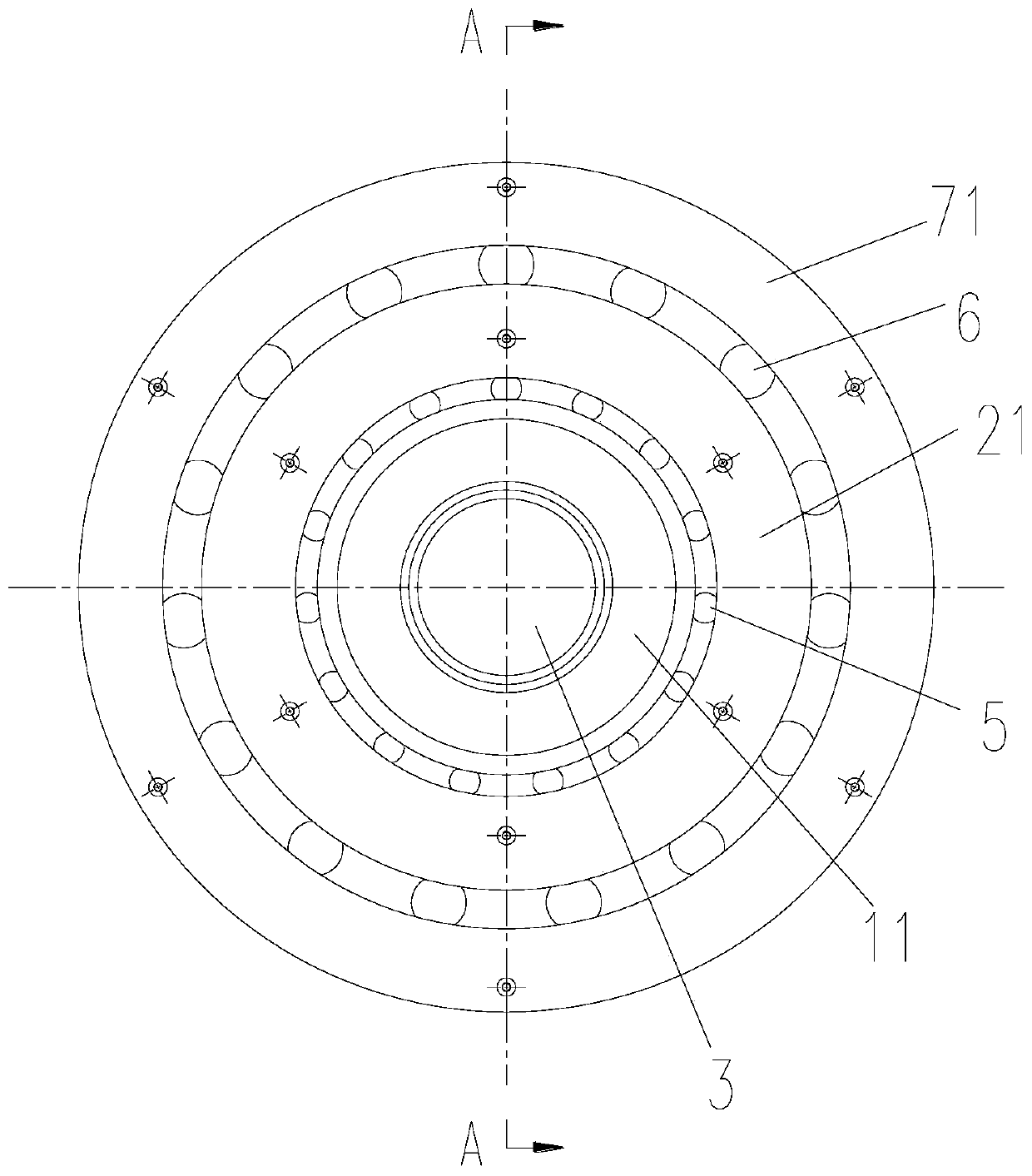
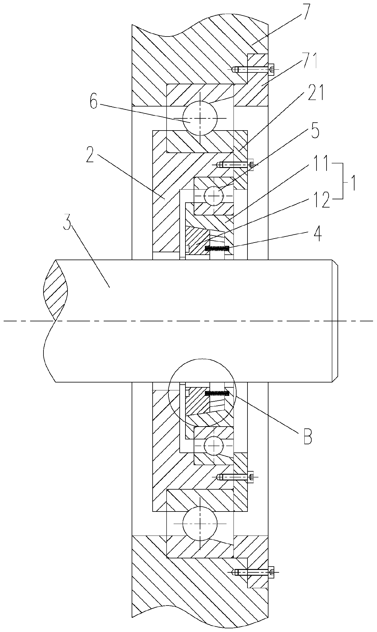
[0043] Such as Figure 1-11 As shown, this embodiment proposes a sliding block clearance protection bearing device, which includes a support assembly 1 and a drive element 2, wherein the support assembly 1 and the drive element 2 are both clearance-fitted on the outer periphery of the rotor 3, and when the rotor 3 loses When electricity is dropped, the driving member 2 can push the support assembly 1 to connect with the rotor 3, so as to support the rotor 3.

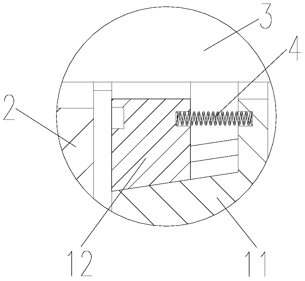
[0044] The support assembly 1 includes a built-in part 11 and at least two sliders 12. The built-in part 11 is clearance-fitted on the outer periphery of the rotor 3. One end of the built-in part 11 has a chute 111 communicating with the rotor 3. At least two sliders 12 are Distributed in the chute 111, and slide in the chute 111 in the direction inclined to the axis of the rotor 3, when the slider 12 slides in the chute 111, the inner end of the slider 12 is in contact with or away from the rotor 3 . Specifically, the...

Embodiment 2

[0053] This embodiment is basically the same as Embodiment 1, the only difference is that the rotor 3 is provided with a third bearing 8, and the slider 12 is arranged on the outer periphery of the third bearing 8 with a gap. Under the push of the driving member 2, the slider 12 The supporting portion of the third bearing 8 is in contact with the outer ring of the third bearing 8 to support the third bearing 8 and thereby realize the support of the rotor 3 .

[0054] Preferably, the outer periphery of the rotor 3 is provided with a stepped surface, and the stepped surface on the rotor 3 cooperates with the sleeve 31 connected thereon to press against the outer periphery of the third bearing 8 to realize the detachable connection of the third bearing 8 . Further preferably, the sleeve 31 is screwed on the outer periphery of the rotor 3 .


PUM


Abstract

The invention relates to a magnetic suspension bearing system, in particular to a protective bearing device with sliding blocks for eliminating a clearance. The protective bearing device comprises a supporting assembly and a driving piece; the supporting assembly is arranged at the outer periphery of a rotor in a clearance manner; the supporting assembly comprises a built-in piece and at least twosliding blocks; a sliding groove communicating with the rotor is formed in the built-in piece; the at least two sliding blocks are circumferentially distributed in the sliding groove and slide in thesliding groove in an inclined direction with the axis of the rotor; when the sliding blocks slide in the sliding groove, the inner ends of the sliding blocks are connected with or far away from the rotor; arc grooves with the axial depths gradually changing are formed in the end faces, positioned at the groove opening of the sliding groove, of the sliding blocks; the driving piece provides synchronous axial pushing force for the at least two sliding blocks; and the driving piece is rotatably connected with the built-in piece, and is provided with insertion columns which correspond to the arcgrooves one by one and are inserted into the arc grooves. The problem that a protective bearing device in the prior art cannot automatically protect the rotor under the condition of power failure is solved.

Description

technical field [0001] The invention relates to a magnetic suspension bearing system, in particular to a sliding block eliminating clearance and protecting a bearing device. Background technique [0002] The magnetic suspension bearing system will lose the bearing capacity of the rotor in the case of power failure, overload, etc., so it is necessary to install a protective bearing device to provide temporary support for the rotor that loses support, so as to prevent the high-speed rotating rotor from falling on the stator and ensure the entire The safety of the magnetic levitation system. At present, the protective bearings used in the magnetic levitation system mostly adopt traditional rolling bearings, but in order to make the magnetic levitation system work normally, there is a fixed gap between the rotor and the inner ring of the rolling bearing. Therefore, when the rotor falls, since the gap between the rotor and the bearing cannot be eliminated, the bearing will be gr...

Claims


Application Information

Patent Timeline
Patent Type & Authority Applications(China)
IPC IPC(8): F16C32/04F16C41/00
CPCF16C32/0442F16C41/00
Inventor 俞成涛谢超祥孙月梅刘凯磊叶霞李秀莲
Owner JIANGSU UNIV OF TECH
Why Eureka
Try Eureka