
Device and method for dynamically testing liquid reactive molding shrinkage

A liquid reaction and molding technology, applied in the direction of material thermal expansion coefficient, etc., can solve the problems of test value interference, difficult to obtain reaction shrinkage, etc., to achieve the effect of eliminating errors and increasing crystallinity

Active Publication Date: 2020-01-03
BEIJING UNIV OF CHEM TECH
View PDF3 Cites 2 Cited by
  • Summary
  • Abstract
  • Description
  • Claims
  • Application Information

AI Technical Summary

Problems solved by technology

However, this method has some disadvantages
First of all, in this method, the liquid resin sample needs to be sucked into the piston barrel through the relevant pipeline, and the resin in the pipeline will also shrink, which will interfere with the final test value; secondly, many of these processing processes need to be heated to a certain degree of reaction Temperature, the thermal expansion and reaction shrinkage of the sample will be reflected on the shrinkage curve eventually, and the mutual interference between them makes it difficult to obtain the real reaction shrinkage in actual operation; Interference removal with extra resin in the tubing for accurate determination of shrinkage during reaction

Method used


Image

  • Device and method for dynamically testing liquid reactive molding shrinkage
  • Device and method for dynamically testing liquid reactive molding shrinkage
  • Device and method for dynamically testing liquid reactive molding shrinkage

Examples


Embodiment Construction

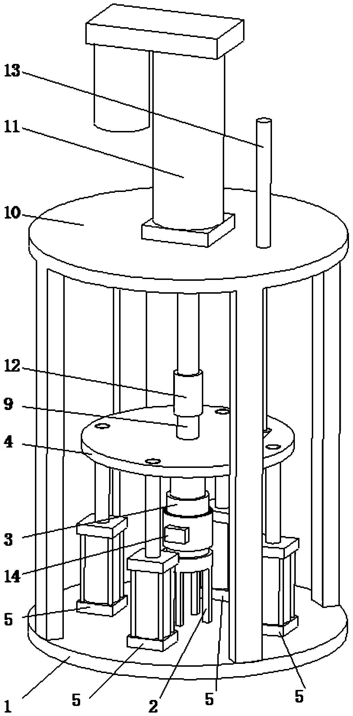
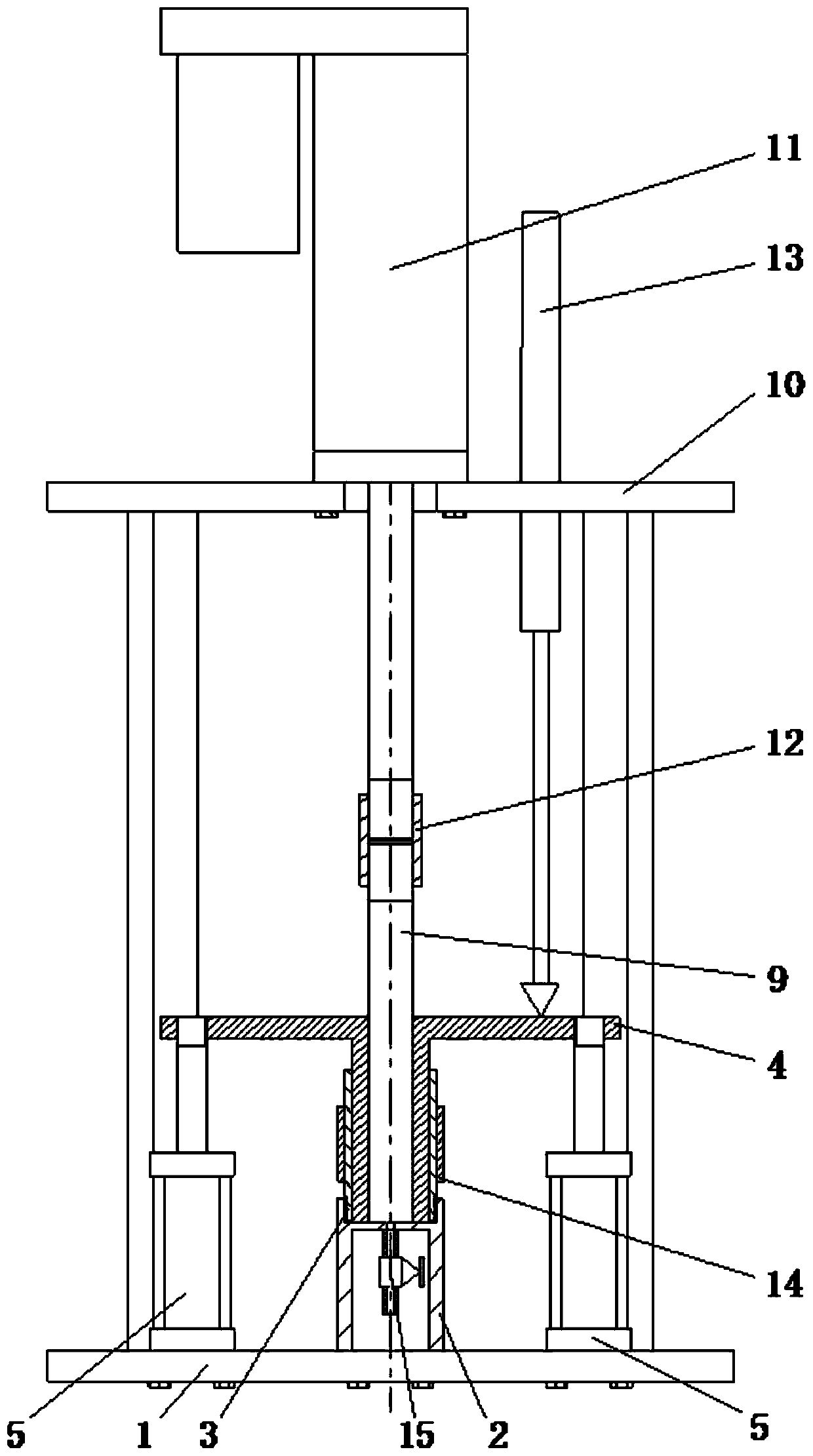
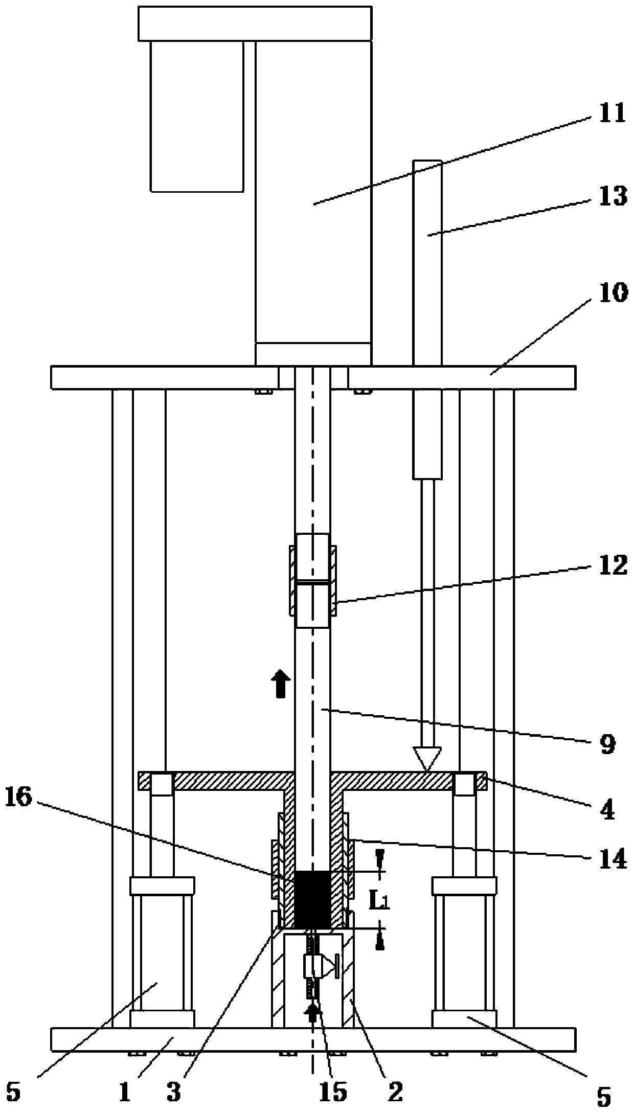
[0020] The present invention proposes a device for dynamically testing liquid reaction molding shrinkage, such as figure 1 ,figure 2, image 3 , Figure 4 , Figure 5 As shown, the module mainly includes: base 1, test chamber fixing seat 2, test chamber 3, annular plunger 4, cylinder 5, sample injection plunger 9, electric cylinder fixing seat 10, electric cylinder 11, coupling 12, The displacement sensor 13, the electric heater 14, the sampling valve 15 and the sample 16 to be tested are composed. Among them, the base 1 is a round thick rigid flat plate, placed on the surface used to place the instrument; the test chamber fixing seat 2 is a metal cylinder with an upright axis, with four legs on the lower part of the cylinder, and a center on the upper surface. A blind hole with internal thread, the bottom surface of the blind hole is flat, and there is a tiny through hole in the center, the four legs of the test cavity fixing seat 2 are welded to the base 1, and the test cav...


PUM


Abstract

The invention provides a device and a method for dynamically testing liquid reactive molding shrinkage. The device comprises a base, a test cavity fixing base, a test cavity, an annular plunger, fourcylinders, a sample injection plunger, an electric cylinder fixing base, an electric cylinder, a coupler, a displacement sensor, an electric heater, a sample injection valve and a to-be-tested sample.The method comprises the steps of sucking the sample into a cylindrical cavity by moving the cylindrical plunger upwards, carrying out preliminary metering, and preheating the sample to a reaction temperature, pushing the sample into an annular cavity around the cylindrical plunger, and pushing the annular plunger to move upwards. The precise size of the sample at the test temperature can be precisely measured according to displacement of the annular plunger, and the displacement of the annular plunger is monitored in real time, thus a real-time shrinkage rate of the sample can be obtained; the size of the sample is metered and measured after the sample is heated until the temperature is stable, and the interference of thermal expansion on the test process is avoided; and the columnar plunger is pressed downwardly to the bottom, so that the sample injection pipeline can be completely isolated from the to-be-tested sample, and the interference of residual liquid in the pipeline to thetest is avoided.

Description

technical field [0001] The invention relates to a device and method for dynamically testing liquid reaction molding shrinkage, belonging to the field of measurement and testing. Background technique [0002] Liquid reaction molding mainly refers to the process of injecting liquid resin raw materials into the mold, curing the liquid resin raw materials by heating or mixing two active components, and finally forming solid products. The outstanding feature of this type of reaction is that it is accompanied by a chemical reaction during the molding process, which will produce a large shrinkage, which will affect the accuracy of the product size. Therefore, the dynamic shrinkage curve of the resin during the curing process is of great significance to the formulation of the specific process, and it is necessary to develop suitable equipment to test it. [0003] The plunger cylinder method is the most commonly used shrinkage test method. This method uses a piston and a piston cyli...

Claims


Application Information

Patent Timeline
Patent Type & Authority Applications(China)
IPC IPC(8): G01N25/16
CPCG01N25/16
Inventor 杨卫民宋乐谢鹏程丁玉梅
Owner BEIJING UNIV OF CHEM TECH
Learn More