
Projection camera lens

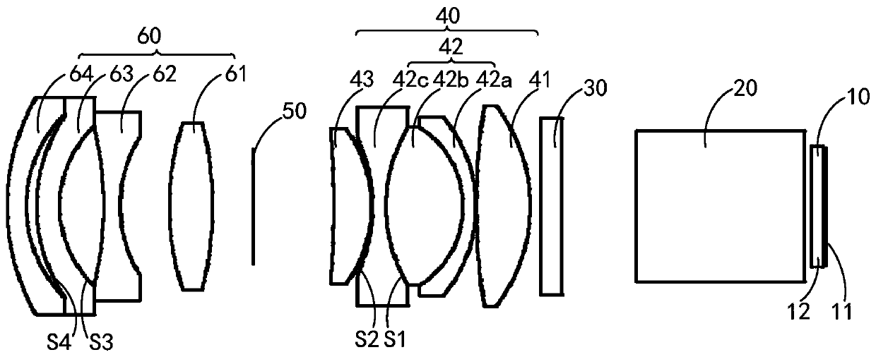
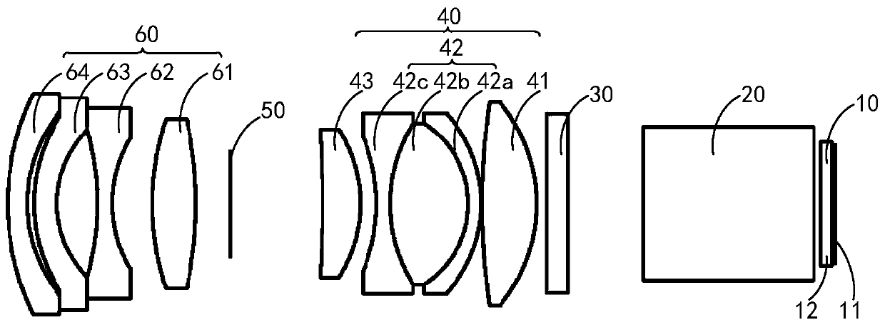
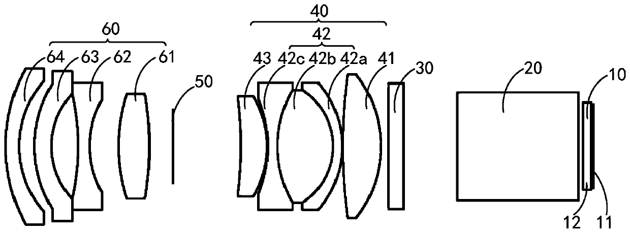
A projection lens and lens technology, applied in the optical field, can solve the problems of increased back focal distance and large size of the projection lens, and achieve the effects of high definition, small size and good correction ability.

Active Publication Date: 2020-01-03
IVIEW DISPLAY SHENZHEN CO LTD
View PDF4 Cites 13 Cited by
  • Summary
  • Abstract
  • Description
  • Claims
  • Application Information

AI Technical Summary

Problems solved by technology

[0003] In the process of implementing the embodiments of the present invention, the inventors have found that there are at least the following problems in the above related technologies: when adding a vibrating mirror between the DMD chip and the prism, the back focus of the projection lens needs to reserve a space for the vibrating mirror. The back focus distance will be greatly increased, and the projection lens will be larger

Method used


Image

  • Projection camera lens
  • Projection camera lens
  • Projection camera lens

Examples


Embodiment Construction

[0029] The present invention will be described in detail below in conjunction with specific embodiments. The following examples will help those skilled in the art to further understand the present invention, but do not limit the present invention in any form. It should be noted that those skilled in the art can make several modifications and improvements without departing from the concept of the present invention. These all belong to the protection scope of the present invention.

[0030] In order to make the purpose, technical solution and advantages of the present application clearer, the present application will be further described in detail below in conjunction with the accompanying drawings and embodiments. It should be understood that the specific embodiments described here are only used to explain the present application, not to limit the present application.

[0031] It should be noted that, if there is no conflict, various features in the embodiments of the present...


PUM


Abstract

The embodiment of the invention relates to the technical field of optics, and discloses a projection camera lens. The projection camera lens comprises a DMD chip, an equivalent prism, a galvanometer,a first refraction lens group, a diaphragm and a second refraction lens group in sequential arrangement, wherein the first refraction lens group comprises a first lens, a triple glued lens and a fifth lens in sequential arrangement; the triple glued lens comprises a second lens, a third lens and a fourth lens; and the fourth lens is an aspherical lens. The triple glued lens can realize good correction capability on spherical aberration, chromatic aberration and secondary spectrum, so that the definition of a projection image emitted from the projection camera lens is high; and the size of theprojection camera lens is small.

Description

technical field [0001] Embodiments of the present invention relate to the field of optical technologies, and in particular to a projection lens. Background technique [0002] With the development of projection technology, the requirements for the definition of projected images are getting higher and higher. In order to realize 4K projection, the current more economical way is to use 0.33 DMD chip, which has 1.05 million micromirrors and can project 1368x768 pixels, and then add a vibrating mirror between the DMD chip and the prism, and through the periodic vibration of the vibrating mirror, the number of pixels can be visually increased to achieve 4K resolution projection imaging. [0003] In the process of implementing the embodiments of the present invention, the inventors have found that there are at least the following problems in the above related technologies: when adding a vibrating mirror between the DMD chip and the prism, the back focus of the projection lens needs...

Claims


Application Information

Patent Timeline
IPC IPC(8): G02B13/00G02B13/18G03B21/00
CPCG02B13/0055G02B13/006G02B13/0065G02B13/0045G03B21/008G02B13/16G03B21/28G03B21/142
Inventor 杨伟樑高志强黄国豹赵远丁明内
Owner IVIEW DISPLAY SHENZHEN CO LTD
Learn More