
Power supply system for converting single-phase electricity into three-phase electricity

A power supply system, three-phase power technology, applied in the direction of conversion equipment, electrical components, circuit devices, etc. that can be converted to DC without intermediate conversion, to achieve the effect of good versatility and easy implementation

Pending Publication Date: 2020-01-03
SOUTHWEST JIAOTONG UNIV
View PDF0 Cites 0 Cited by
  • Summary
  • Abstract
  • Description
  • Claims
  • Application Information

AI Technical Summary

Problems solved by technology

[0006] The purpose of the present invention is to provide a power supply system for converting single-phase power to three-phase power, which can effectively solve the technical problems of single-phase line transmission and three-phase power consumption

Method used


Image

  • Power supply system for converting single-phase electricity into three-phase electricity
  • Power supply system for converting single-phase electricity into three-phase electricity
  • Power supply system for converting single-phase electricity into three-phase electricity

Examples


Embodiment 1

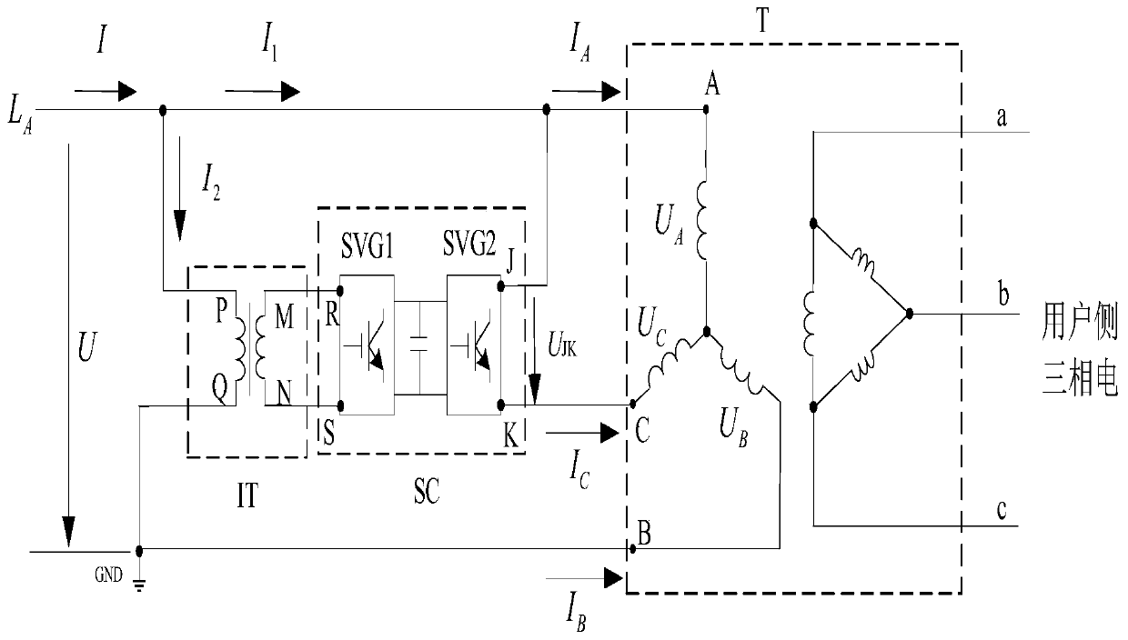
[0028] like figure 1 As shown, the embodiment of the present invention provides a power supply system for converting single-phase electricity to three-phase electricity, wherein the system includes a transmission line L A , isolation transformer IT, power converter SC and three-phase transformer T, isolation transformer IT and transmission line L A connection, the power converter SC is connected to the isolation transformer IT, and the three-phase transformer T is connected to the transmission line L AIt is connected to the power converter SC, and the terminal a, terminal b and terminal c of the delta winding of the three-phase transformer T are connected to the low-voltage distribution network with the neutral point grounded.

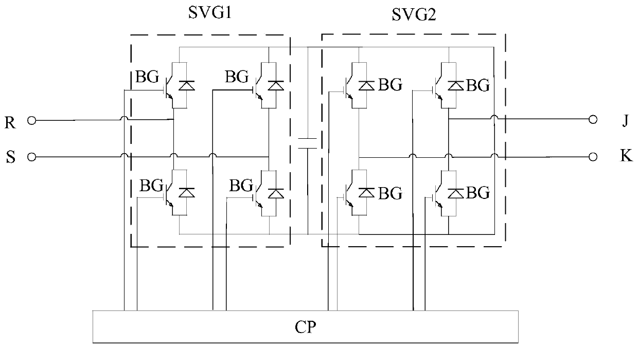
[0029] like figure 2 As shown, the P terminal of the input terminal of the isolation transformer IT is connected to the power line L A connection, the Q terminal of the isolation transformer IT is grounded to GND; the M terminal and the N terminal ...

Embodiment 2

[0036] like figure 1 As shown, the embodiment of the present invention provides a power supply system for converting single-phase electricity to three-phase electricity, wherein the system includes a transmission line L A , isolation transformer IT, power converter SC and three-phase transformer T; isolation transformer IT and transmission line L A connection, the power converter SC is connected to the isolation transformer IT, and the three-phase transformer T is connected to the transmission line L A Connected to the power converter SC.

[0037] like Figure 4 As shown, the main difference between the embodiment of the present invention and the above-mentioned embodiment is that the terminal B of the star winding of the three-phase transformer T in this system passes through the return line L B Connect to the Q terminal of the power converter SC. Other structures and features are the same as those in the first embodiment above, and will not be repeated here. In the embo...


PUM


Abstract

The invention discloses a power supply system for converting single-phase electricity into three-phase power, and belongs to the technical field of power grid power supply and distribution. A terminalP at the input end of an isolation transformer IT is connected with a power transmission line LA, and a terminal Q is grounded; a terminal M and a terminal N at the output end of the isolation transformer IT are respectively connected with a terminal R and a terminal S at the input end of a corresponding power converter SC; the terminal A of the star-shaped winding of a three-phase transformer Tis connected with a power transmission line LA, the terminal C of the star-shaped winding of the three-phase transformer T is connected with a terminal J at the output end of the power converter SC, and the terminal B of the star-shaped winding of the three-phase transformer T is grounded, and is connected with the terminal Q of the isolation transformer IT through a return line LB; and the terminal a, the terminal b and the terminal c of the triangular winding of a three-phase transformer T are connected with a low-voltage power distribution network with a grounded neutral point.

Description

technical field [0001] The invention relates to the technical field of electric power grid power supply and distribution. Background technique [0002] Users in the field of low-voltage power distribution in my country generally use single-phase power supply. When users need to use three-phase power, they need to re-erect power lines, which is very troublesome and takes a long time; Two-phase transmission lines, single-phase transformers are connected to users, which is more economical and does not take up space, but some users need three-phase power. In particular, the user needs to use the three-phase power supply for a short period of time due to special reasons, and the time for erecting a new three-phase line is not allowed. If the power quality of the grid allows, the three-phase power supply can be provided relatively easily, which will have a greater impact economic and social value. [0003] In the power distribution system, due to long-term mechanical force, elect...

Claims


Application Information

Patent Timeline
Patent Type & Authority Applications(China)
IPC IPC(8): H02J3/00H02J3/18H02M5/14H02M5/458
CPCH02J3/00H02J3/1842H02M5/14H02M5/4585Y02E40/30
Inventor 易东李群湛黄小红解绍锋郭锴张丽艳
Owner SOUTHWEST JIAOTONG UNIV
Learn More