An ecological roof light-controlled watering system for sponge city construction

A sponge city, roof light technology, applied in construction, application, drinking water installations, etc., can solve the problem of inconvenient watering of ecological roof water storage tanks, achieve good watering effect and increase the amount of light.

Active Publication Date: 2021-08-03
汇张思建筑设计事务所(上海)股份有限公司
View PDF5 Cites 0 Cited by
  • Summary
  • Abstract
  • Description
  • Claims
  • Application Information

AI Technical Summary

Problems solved by technology

[0005] The purpose of the present invention is to provide an automatic, time-saving and labor-saving ecological roof light-controlled watering system for sponge city construction to solve the problem of inconvenient watering in existing ecological roof tanks

Method used


Image

  • An ecological roof light-controlled watering system for sponge city construction
  • An ecological roof light-controlled watering system for sponge city construction
  • An ecological roof light-controlled watering system for sponge city construction

Examples


Embodiment 1

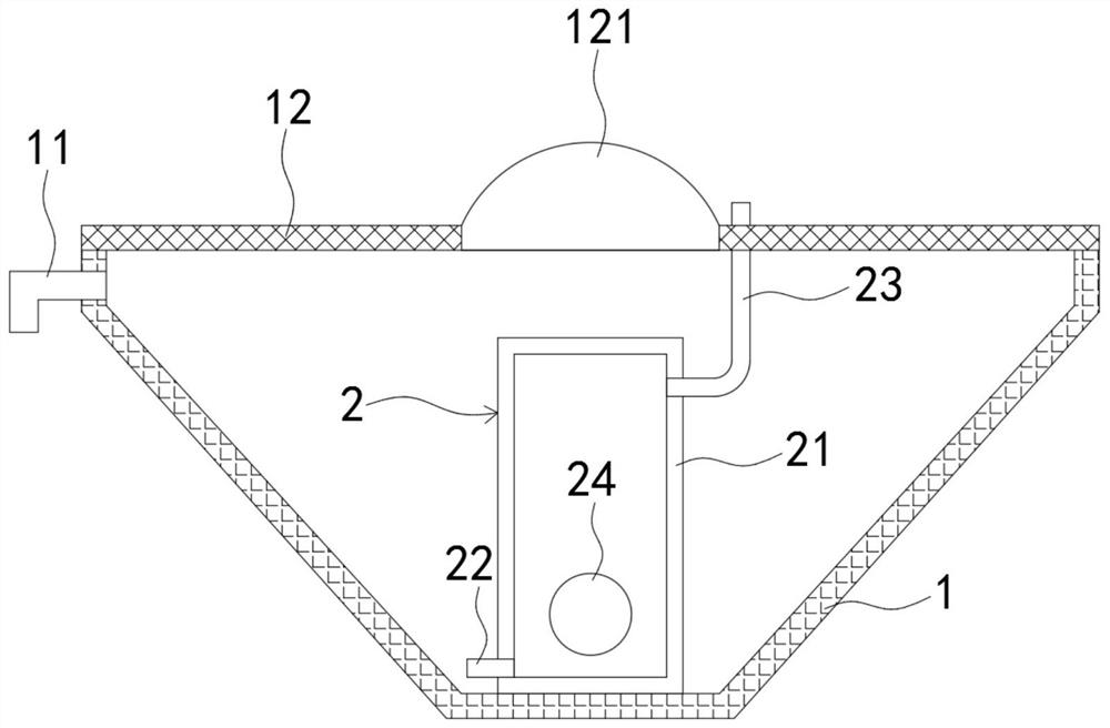
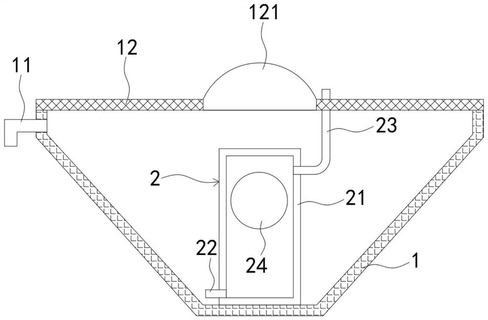
[0031] Such as Figure 1-2 As shown, an ecological roof light-controlled irrigation system for sponge city construction includes a water storage tank 1. The water storage tank 1 is arranged in a large upper part and a smaller one at the lower part to facilitate the collection of rainwater. The water storage tank 1 is provided with:

[0032] The overflow pipe 11, the overflow pipe 11 is arranged on the top of the water storage tank 1 close to the opening, the output end of the overflow pipe 11 is downward, which can prevent dust or other sundries from blocking the overflow pipe 11, and the overflow pipe 11 is close to the roof drain pipe. Water inlet settings;

[0033] The permeable net 12, the permeable net 12 covers the upper opening of the water storage tank 1, which can prevent sundries such as fallen leaves from entering the water storage tank 1 and improve the water quality. It needs to be explained that the permeable net 12 is embedded with a transparent plate 121, the ...

Embodiment 2

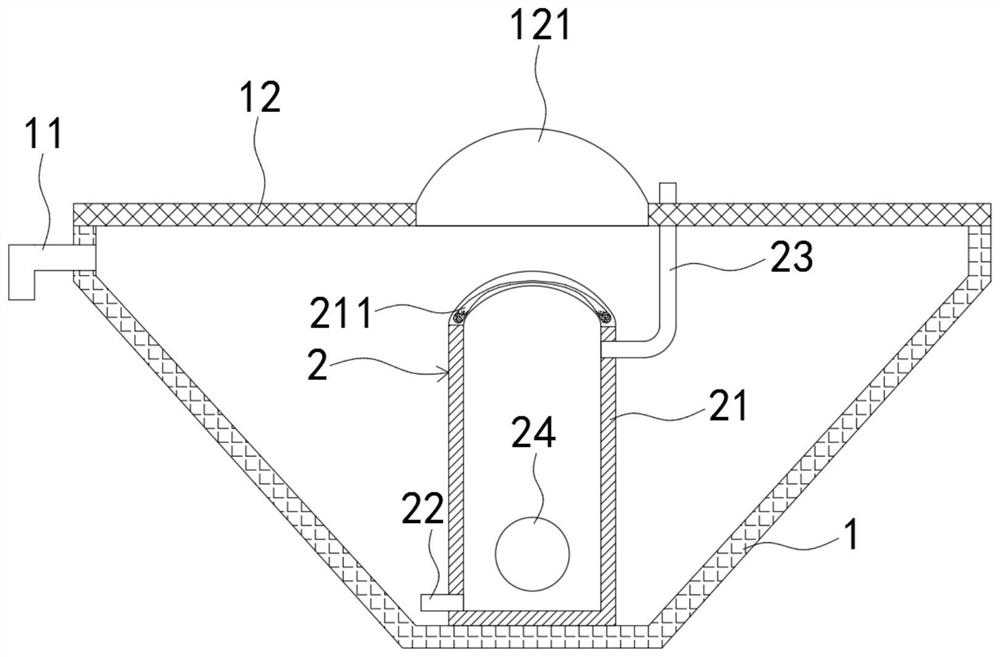
[0042] Such as Figure 3-6 As shown, the difference between this embodiment and Embodiment 1 is that: the upper end of the sealing shell 21 protrudes upwards to form a spherical surface, and a storage cavity 211 is provided in the upper side wall of the sealing shell 21, and the storage cavity 211 includes a storage cavity corresponding to the spherical surface. , an upwardly raised spherical cavity 2111 and an annular cavity 2112 connected to the bottom of the spherical cavity 2111 (such as Figure 5 As shown), the storage cavity 211 is filled with iron powder, and the iron powder will be collected in the annular cavity 2112 under the action of gravity, and the optical expansion ball 24 is embedded with a permanent magnet block (not shown).

[0043] In this embodiment, when the volume of the light expansion ball 24 becomes larger and the buoyancy becomes larger and moves upward to the uppermost end of the sealed shell 21 (such as Figure 4 As shown), since the light expansio...


PUM


Abstract

The invention belongs to the field of sponge city construction, and in particular relates to an ecological roof light-controlled irrigation system for sponge city construction. The upper part of the water storage tank is close to the opening, and the output end of the overflow pipe is downward; the permeable net covers the upper opening of the water storage tank, and the permeable net and the water storage tank are detachably connected; the water storage tank is equipped with a water pressure mechanism. The water mechanism includes: a sealed shell, the top of which is made of transparent material, and the sealed shell is fixedly connected to the bottom surface of the water storage tank; a one-way water inlet pipe, which is connected to the lower part of the sealed shell; The drain pipe is connected to the upper part of the sealed case, and the upper end of the one-way drain pipe extends to the outside of the water storage tank. The invention utilizes the properties of the light-expanding ball to expand when exposed to light and recover without light, cooperates with a one-way water inlet pipe and a one-way drain pipe to squeeze out the water in the water storage tank to realize the effect of automatic watering.

Description

technical field [0001] The invention belongs to the field of sponge city construction, and in particular relates to an ecological roof light-controlled watering system for sponge city construction. Background technique [0002] In the construction of the sponge city, the ecological roof plays an important role. The greening of the roof can not only increase the urban green area, reduce the urban heat island effect, but also beautify the city, purify the air, and effectively improve people's living environment and quality of life. [0003] During the construction process of the existing ecological roof, it is usually equipped with a water storage tank for collecting rainwater. However, the structure of the water storage tank is simple and the function is relatively single, which can only meet the most basic water storage function. Watering the ecological roof plants When using water pumps, it is usually necessary to set additional equipment such as water pumps, which not only...

Claims


Application Information

Patent Timeline
Patent Type & Authority Patents(China)
IPC IPC(8): A01G27/00E03B3/02
CPCA01G27/00A01G27/003A01G27/008E03B3/02Y02A20/108
Inventor 王瑞常友
Owner 汇张思建筑设计事务所(上海)股份有限公司
Why Eureka
Try Eureka