Nondestructive testing robot system and method for aircraft skin surface defects

A robotic system, aircraft skin technology, applied in aircraft component testing, optical testing flaws/defects, instruments, etc., can solve the problems of accelerated crack deterioration, manual inspection by technicians, easy loss, error, leakage, etc., to meet the smart effect

Pending Publication Date: 2020-01-07
西安航通测控技术有限责任公司
View PDF0 Cites 9 Cited by
  • Summary
  • Abstract
  • Description
  • Claims
  • Application Information

AI Technical Summary

Problems solved by technology

Especially in the harsh flight environment, it will further accelerate the deterioration of cracks and promote corrosion. The occurrence of these defects will destroy the integrity of the aircraft skin structure and cause a decrease in structural strength, which is one of the main reasons for flight accidents
[0004] At present, most of my country's aviation manufacturing enterprises have generally introduced digital measurement equipment for surface defect detection of aircraft skins, such as laser radar, laser tracker, total station, etc., and are gradually getting rid of the past detection methods that rely on mold lines, templates and other process equipment , but still mainly manual detection by technicians
Manual detection is closely related to the experience and sense of responsibility of technicians, and has great limitations. It is prone to problems such as loss, error, and omission. It is urgent to use automatic detection to replace manual detection.

Method used


Image

  • Nondestructive testing robot system and method for aircraft skin surface defects
  • Nondestructive testing robot system and method for aircraft skin surface defects
  • Nondestructive testing robot system and method for aircraft skin surface defects

Examples


Embodiment Construction

[0045]In order to make the technical problems, technical solutions and beneficial effects to be solved by the present invention clearer, the present invention will be further described in detail below in conjunction with the accompanying drawings and embodiments. It should be understood that the specific embodiments described here are only used to explain the present invention, not to limit the present invention.

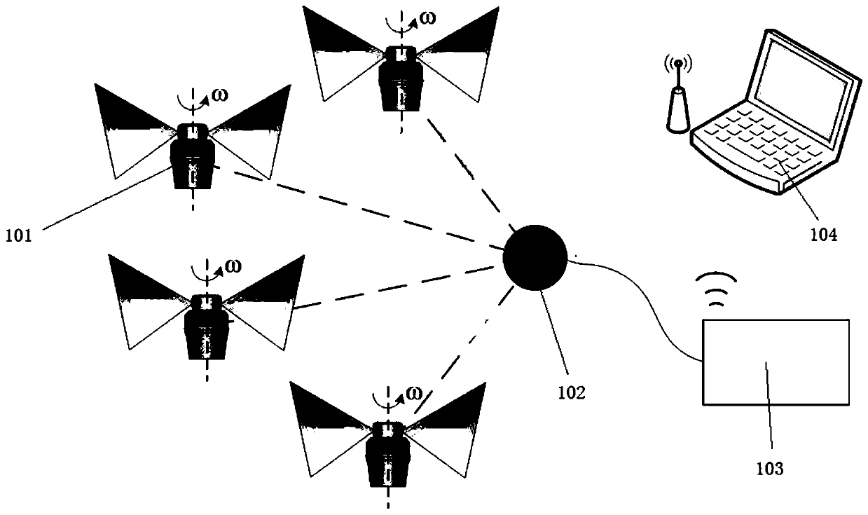
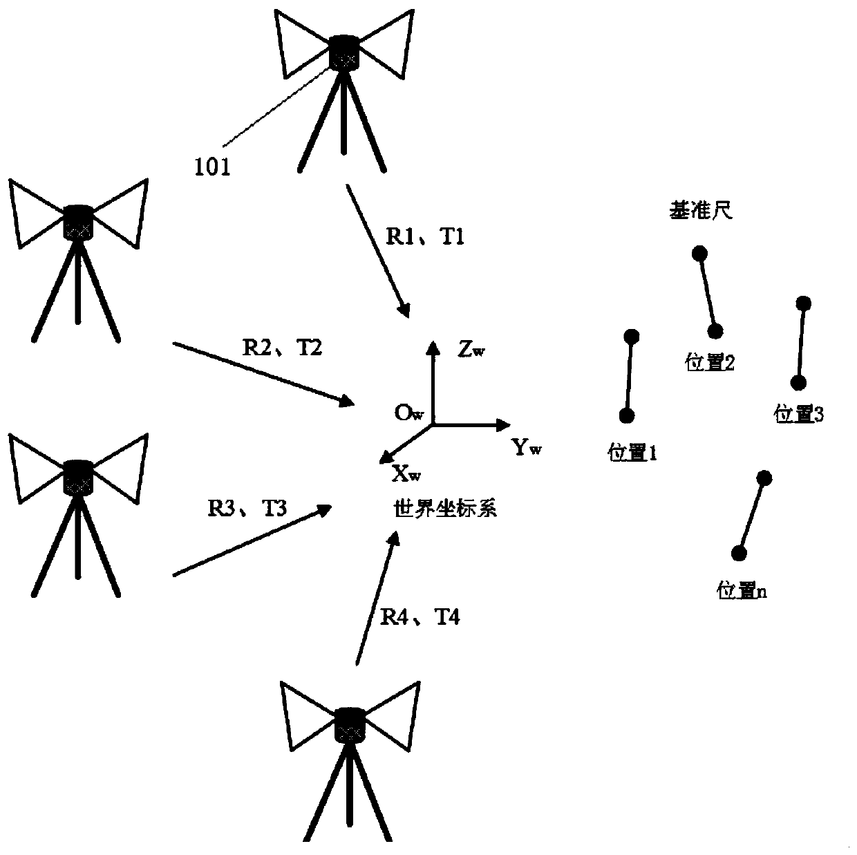
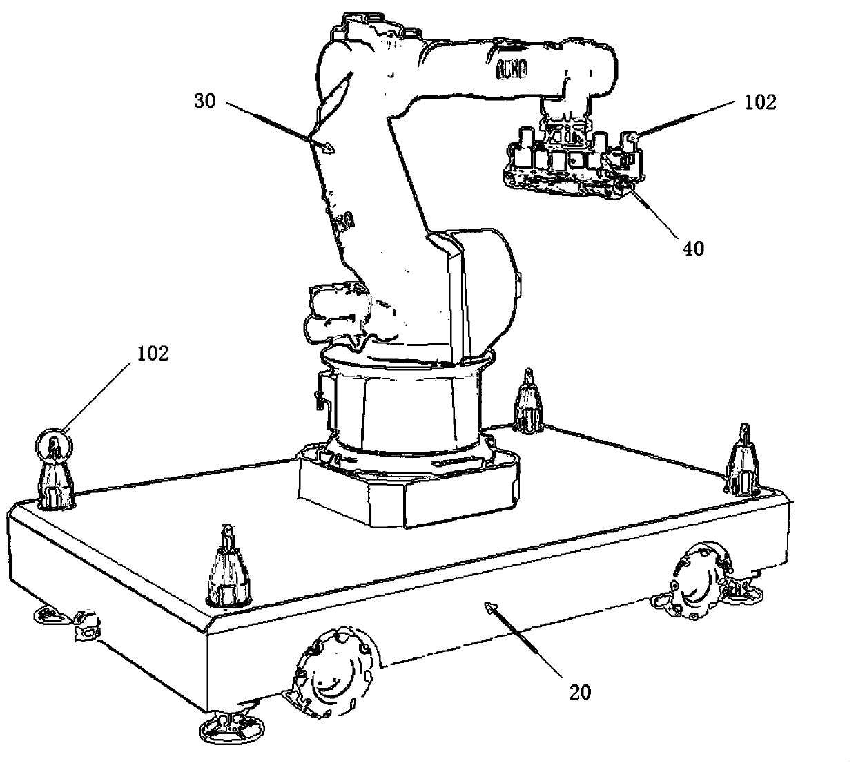
[0046] Such as image 3 As shown, in an embodiment provided by the present invention, a robot system for non-destructive testing of aircraft skin surface defects includes a multi-base laser scanning full-space positioning system 10, an AGV trolley 20, a six-degree-of-freedom mechanical arm 30, and a terminal binocular Structured light measurement sensor 40, software system 50; during the detection process of aircraft skin surface defects, global positioning is performed by multi-base laser scanning full-space positioning system 10;

[0047] Such as figure 1 with ...


PUM


Abstract

The invention relates to the field of the large-size space measuring and positioning technology and the nondestructive testing technology, and particularly discloses a nondestructive testing robot system for aircraft skin surface defects. The nondestructive testing robot system comprises a multi-base-station laser scanning total space positioning system, an AGV, a six-freedom-degree mechanical arm, a tail end binocular structure light measuring sensor and a software system. The embodiment of the invention further provides a nondestructive testing method for the aircraft skin surface defects. The nondestructive testing method comprises the following specified steps that S10, a space measuring field is set up; S20, digital definition is carried out; S30, route planning is carried out; S40, measurement is implemented; S50, data processing is carried out; and S60, a report is generated. According to the nondestructive testing robot system and method for the aircraft skin surface defects, the intelligent testing robot system with submillimeter-scale large space intelligent positioning and navigation, global precision three-dimensional automatic measurement, aircraft skin surface defectvisual detection and recognition and other functions is achieved, and the intelligent, automatic and high-precision three-dimensional measurement application needs for the aircraft skin surface defects are met.

Description

technical field [0001] The invention relates to the fields of large-scale space measurement and positioning technology and non-destructive testing technology, in particular to a robot system and method for non-destructive testing of aircraft skin surface defects. Background technique [0002] With the rapid development of my country's aviation equipment research and development information application technology level, the continuous improvement of aircraft equipment performance has put forward higher requirements for its detection technology, and there is an urgent need for corresponding detection technology to move towards intelligent, integrated, digital, and online directions. Fast forward. [0003] The reason for the damage and defects of the aircraft skin surface is that the aircraft will experience a process of pressurization and decompression every time it takes off and lands, which makes the skin surface periodically expand and contract, which leads to the fatigue of...

Claims


Application Information

Patent Timeline
IPC IPC(8): B64F5/60G01N21/88G01N21/01B25J11/00
CPCB64F5/60G01N21/8851G01N21/01B25J11/00
Inventor 钟征宇刘青潘晓贾昆
Owner 西安航通测控技术有限责任公司
Why Eureka
Try Eureka