Constant-humidity machine water tank for showcase

A technology of constant humidity machine and water tank, which is applied in the direction of water saving, display cabinets, applications, etc. It can solve the problems of fixed structure, water addition, and affecting the use efficiency of instruments, so as to achieve the effect of increasing efficiency and increasing process

Inactive Publication Date: 2020-01-07
安徽中博智能科技有限公司
View PDF0 Cites 0 Cited by
  • Summary
  • Abstract
  • Description
  • Claims
  • Application Information

AI Technical Summary

Problems solved by technology

Most of the water tanks of existing dehumidifiers have fixed structures. After a long time of operation, the staff cannot add water to the water tanks in time, resulting in empty operation of the constant humidity machine, which affects the efficiency of the instrument.

Method used


Image

  • Constant-humidity machine water tank for showcase
  • Constant-humidity machine water tank for showcase
  • Constant-humidity machine water tank for showcase

Examples


Embodiment 1

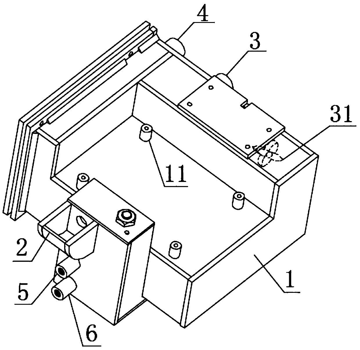
[0036] A water tank for a constant humidity machine for a display cabinet, comprising a water storage tank, the water storage tank includes a main box body 1, a water inlet 2, an air inlet pipe 3, an air outlet pipe 4, an overflow port 5 and a water discharge port 6, and the main box body 1 The top surface is provided with a main board fixing column 11 and a liquid level control switch. Both the air inlet pipe 3 and the air outlet pipe 4 are fixedly connected to the main box body 1. The inlet of the air inlet pipe 3 is provided with a fan 31, and the air outlet pipe 4 is connected to the display cabinet. The body is connected, and the drain port 6 is equipped with a suction pipe.

[0037] The water storage tank is assembled inside the ZB-HC-004 micro-environment intelligent constant humidity machine to store water. Add water from the water inlet 2 to the main box body 1, start the constant humidity machine, and under the action of the fan 31, the display cabinet body The air e...

Embodiment 2

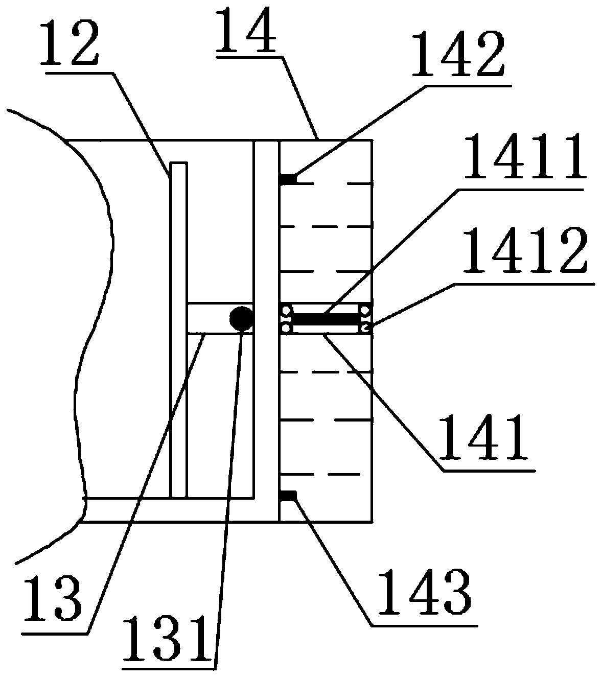
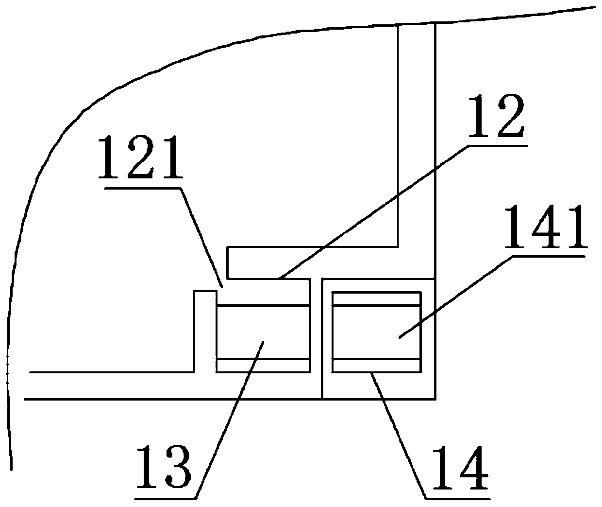
[0039] A water tank for a constant humidity machine for a display cabinet, comprising a water storage tank, the water storage tank includes a main box body 1, a water inlet 2, an air inlet pipe 3, an air outlet pipe 4, an overflow port 5 and a water discharge port 6, and the main box body 1 The top surface is provided with a main board fixing column 11 and a liquid level control switch. The liquid level control switch includes a monitoring tank 12, an inner floating plate 13 and a monitoring cylinder 14. The monitoring tank 12 is provided with a side channel 121, and the inner floating plate 13 is inlaid with a permanent magnet. Ring 131, monitoring tube 14 includes filling liquid, outer floating plate 141, upper pressure sensor 142, lower pressure sensor 143, alarm 144 and alarm power supply 145, outer floating plate 141 is provided with soft magnetic sheet 1411 and ball 1412, upper pressure The sensor 142 and the down pressure sensor 143 are electrically connected with the al...

Embodiment 3

[0042] A water tank for a constant humidity machine for a display cabinet, comprising a water storage tank, the water storage tank includes a main box body 1, a water inlet 2, an air inlet pipe 3, an air outlet pipe 4, an overflow port 5 and a water discharge port 6, and the main box body 1 The top surface is provided with a main board fixing column 11, a liquid level control switch, a long baffle 15 and a short baffle 16, and the water inlet 2 includes a water inlet pipe 21, a ceramic filter element 22 and a water inlet cover 23, and the ceramic filter element 22 is screwed to the water inlet pipe 21 , one end of the water inlet cover 23 is rotationally connected with the water inlet pipe 21, the other end of the water inlet cover 23 is magnetically attracted to the water inlet pipe 21, the air inlet pipe 3 and the air outlet pipe 4 are fixedly connected with the main box body 1, and the air inlet pipe The entrance of 3 is provided with a fan 31, the air outlet pipe 4 is conne...


PUM


Abstract

The invention relates to the technical field of constant-humidity machine water tanks, and particularly relates to a constant-humidity machine water tank for a showcase. The water tank comprises a water storage tank, wherein the water storage tank comprises a main tank body, a water inlet, an air inlet pipeline, an air outlet pipeline, a water overflow port and a drainage port, the top surface ofthe main tank body is provided with a main plate fixing column and a liquid level control switch, the air inlet pipeline and the air outlet pipeline are fixedly connected with the main tank body, theinlet of the air inlet pipeline is provided with a fan, the air outlet pipeline is connected with a showcase body, and the drainage port is provided with a straw. According to the water tank, water isfiltered through a ceramic filter element of the water inlet, the inner wall of the main tank body is prevented from scaling, through a lower pressure sensor and an alarm of the liquid level controlswitch, a worker is reminded to timely add water, through an upper pressure sensor and the alarm of the liquid level control switch, the worker is reminded to stop adding water in time, the situationthat water adding is not limited, and redundant water is discharged from the overflow port is avoided, water source waste is reduced, and the running efficiency of a constant-humidity machine is improved.

Description

technical field [0001] The invention relates to the technical field of a water tank for a constant humidity machine, in particular to a water tank for a constant humidity machine used in a showcase. Background technique [0002] At present, in many fields of the national economy, the temperature and humidity requirements for the environment are getting higher and higher, such as aerospace, medicine, electronic product processing, cultural relics archives protection, special material laboratories, etc., all need to have a corresponding temperature and humidity environment, Especially the display cabinets used by museums and archives have the functions of displaying cultural relics and protecting cultural relics. The common method is to install a small constant temperature and humidity machine under the cabinet body of the display cabinet. Most of the water tanks of the existing dehumidifiers have fixed structures. After a long time of operation, the staff cannot add water to ...

Claims


Application Information

Patent Timeline
Patent Type & Authority Applications(China)
IPC IPC(8): E03B11/02A47F3/04C02F1/00G08B21/24
CPCA47F3/04C02F1/001C02F2303/04E03B11/02G08B21/24Y02A20/00
Inventor 赵纯孙越谷峰
Owner 安徽中博智能科技有限公司
Why Eureka
Try Eureka