

Assembled steel structural building
A steel structure, prefabricated technology, used in buildings, building components, building structures, etc., can solve the problems of no auxiliary support, inconvenient disassembly and assembly, etc., to improve aesthetics, facilitate disassembly and assembly, good support effect
- Summary
- Abstract
- Description
- Claims
- Application Information
AI Technical Summary
Problems solved by technology
Method used
Image

Examples
specific Embodiment approach 1
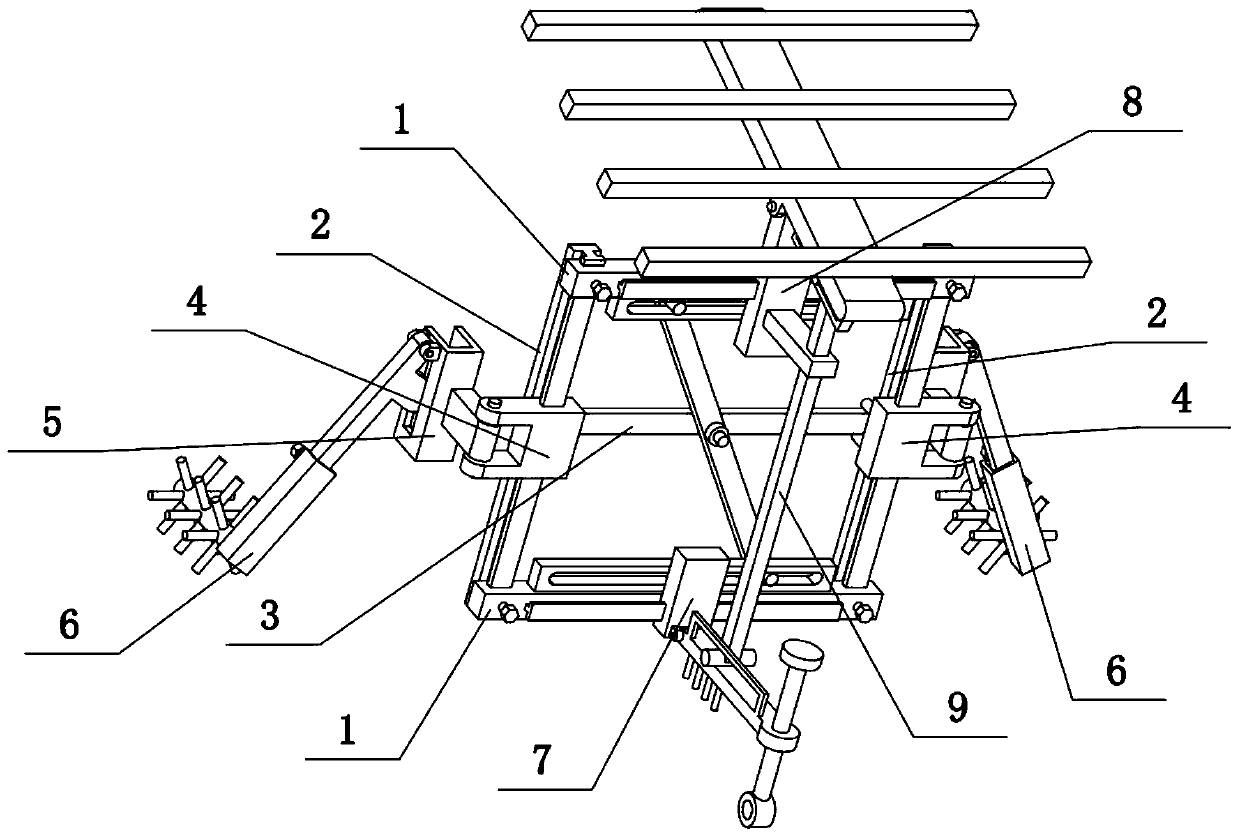
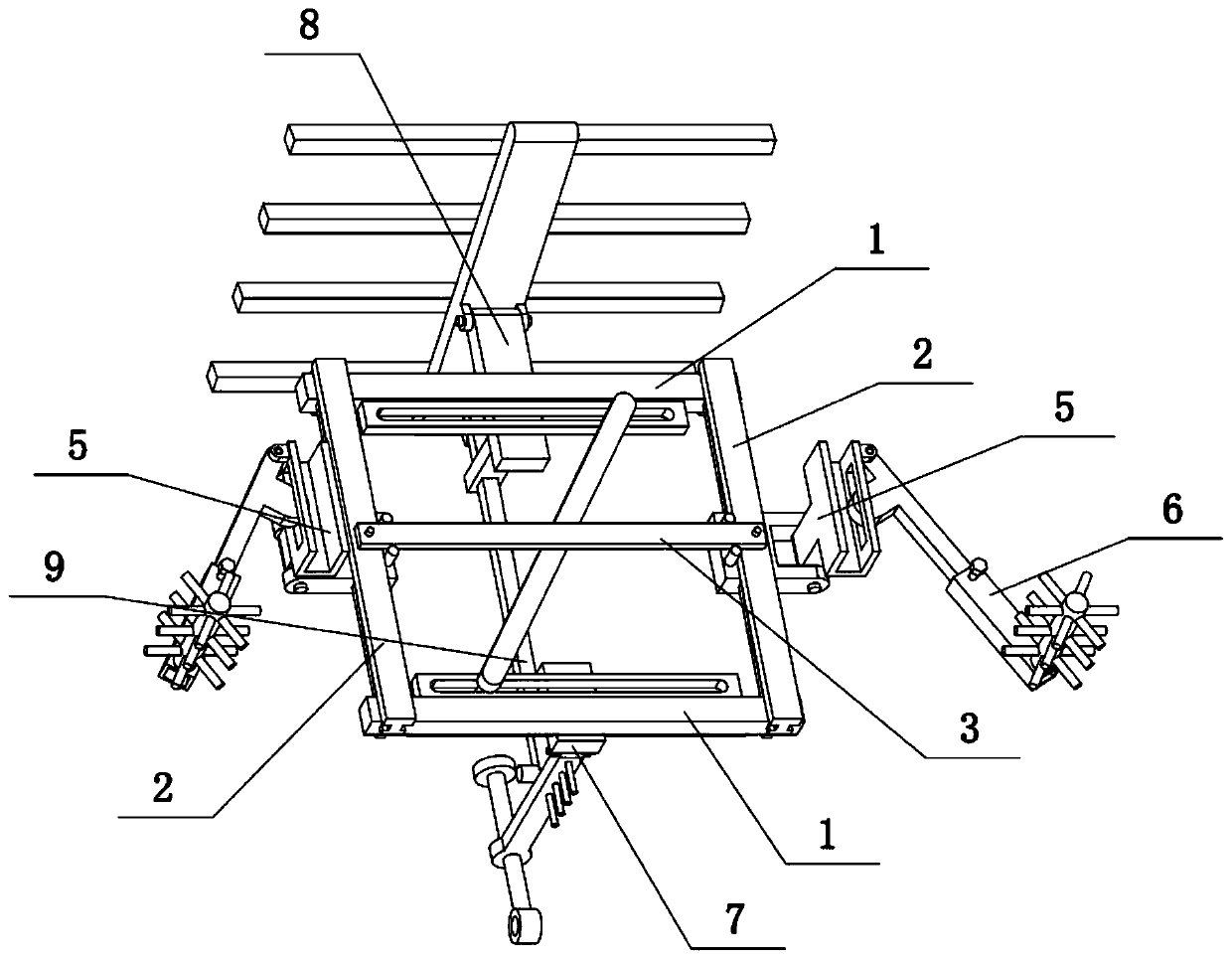
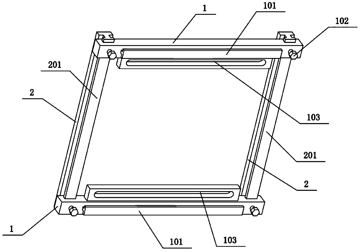
[0033] Combine below Figure 1-10 Describe this embodiment. The present invention relates to a steel structure building, more specifically, an assembled steel structure building, including a horizontal steel beam 1, fastening screws I102, horizontal sliding holes 103, vertical steel beams 2, trapezoidal convex Bar II201, threaded hole 202, middle strip 3, central axis 301, sliding column 302 and inclined steel beam 303, the present invention is convenient to disassemble and assemble, and the supporting property of the present invention is good.
[0034]There are two vertical steel beams 2 on the left and right, trapezoidal convex lines II201 are arranged on the front sides of the two vertical steel beams 2, two horizontal steel beams 1 are arranged on the upper and lower sides, and the left and right ends of the horizontal steel beam 1 at the upper end They are respectively slidably connected to the upper ends of the two trapezoidal convex strips II201, and the left and right ...
specific Embodiment approach 2
[0036] Combine below Figure 1-10 To illustrate this embodiment, the prefabricated steel structure building also includes a movable hinged seat 4, a hinged groove 402, a door-shaped groove 5 and a hinged projection 501, and two movable hinged seats 4 are arranged on the left and right, and two movable hinged seats 4 Slidingly connected to the two trapezoidal protrusions II201 respectively, the outer ends of the two movable hinged seats 4 are provided with hinged grooves 402, and the two door-shaped grooves 5 are fixedly connected with hinged projections 501, and the two hinged projections 501 are hingedly connected to the two hinged slots 402 respectively. The two door-shaped slots 5 can be rotated at the two hinged grooves 402 respectively by the hinged projections 501 thereon, and the two door-shaped slots 5 can be inserted into a wallboard in a vertical direction respectively, and the two door-shaped slots The rotatable effect of the groove part 5 is to adjust the placemen...
specific Embodiment approach 3
[0038] Combine below Figure 1-10 To illustrate this embodiment, the prefabricated steel structure building also includes a rectangular through hole 502, an oblique support rod 503 and a convex pressure block 504, and the two door-shaped groove parts 5 are provided with a rectangular through hole 502, and the two oblique support rods The upper ends of the 503 are respectively hingedly connected to the upper ends of the two door-shaped groove parts 5, and the upper parts of the two oblique support rods 503 are fixedly connected with convex pressing blocks 504, and the two convex pressing blocks 504 are respectively inserted into the two rectangular through holes 502. . The upper ends of the two oblique support rods 503 can rotate on the upper ends of the two door-shaped groove parts 5 respectively, and the lower ends of the two oblique support rods 503 can be supported on the ground, and the convex pressing blocks on it can be driven when the oblique support rods 503 are rotate...
PUM
 Abstract
Description
Claims
Application Information