Supercharge Your Innovation With Domain-Expert AI Agents!

Indoor painting equipment

An equipment and mixing chamber technology, which is applied in the field of indoor painting equipment, can solve the problems of precipitation, uneven painting, and hard blocks in the coating.

Active Publication Date: 2020-01-07
广东穗合建筑装饰有限公司
View PDF6 Cites 4 Cited by
  • Summary
  • Abstract
  • Description
  • Claims
  • Application Information

AI Technical Summary

Problems solved by technology

[0002] During indoor painting work, it is often encountered that the paint has precipitation and hard lumps, resulting in uneven painting. Too much paint is applied at one time, which leads to waste of paint and uneven wall painting. The invention solves the above problems

Method used


Image

  • Indoor painting equipment
  • Indoor painting equipment
  • Indoor painting equipment

Examples


specific Embodiment approach 1

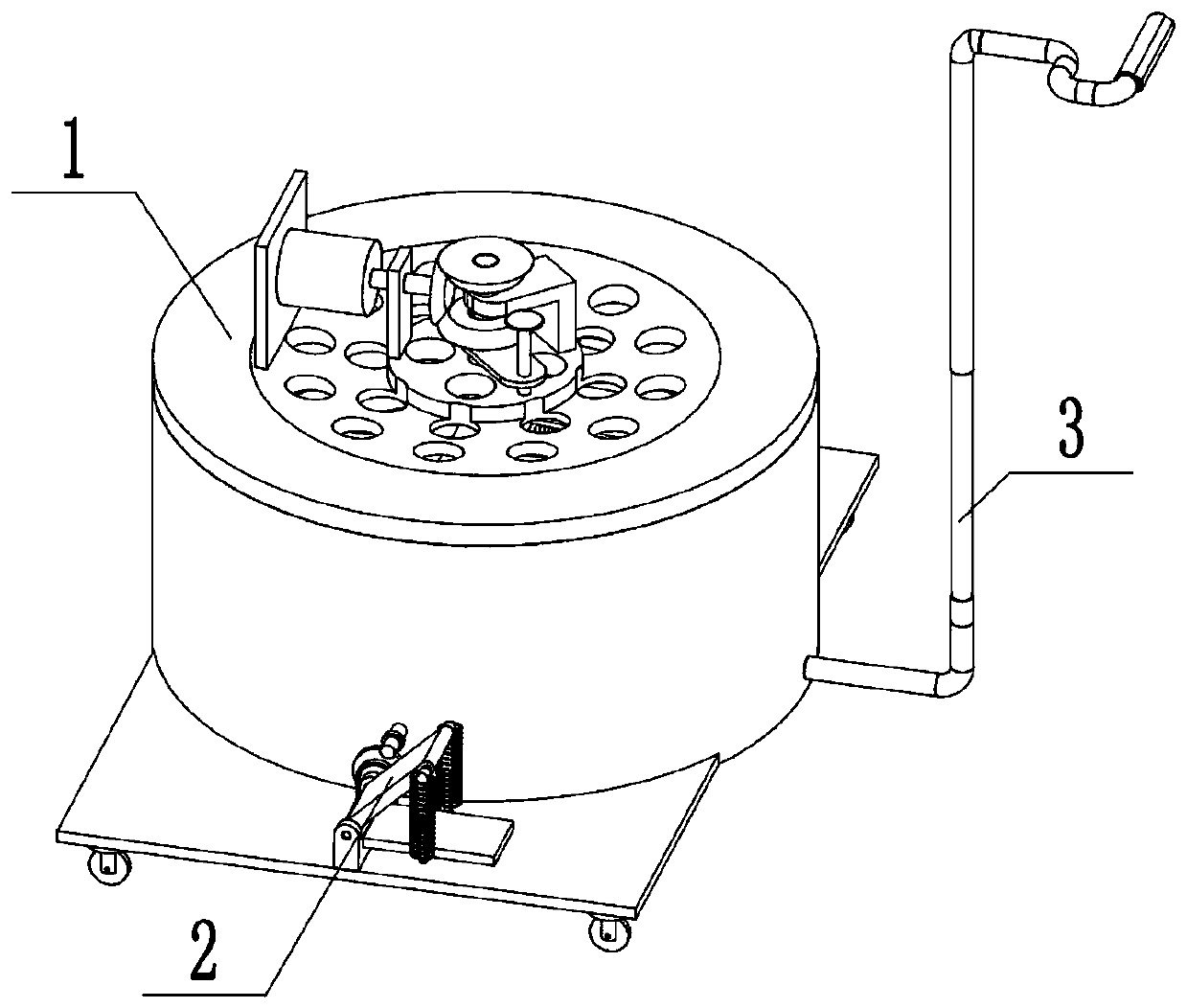
[0032] Combine below Figure 1-18 In this embodiment, an indoor painting equipment includes a stirring assembly 1, a screen cleaning assembly 2, and a painting assembly 3. It is characterized in that: the stirring assembly 1 is connected to the screen cleaning assembly 2, and the painting assembly Body 3 is connected with stirring assembly 1.

specific Embodiment approach 2

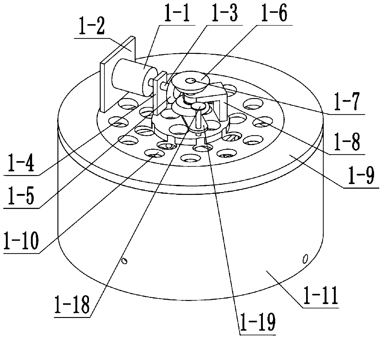
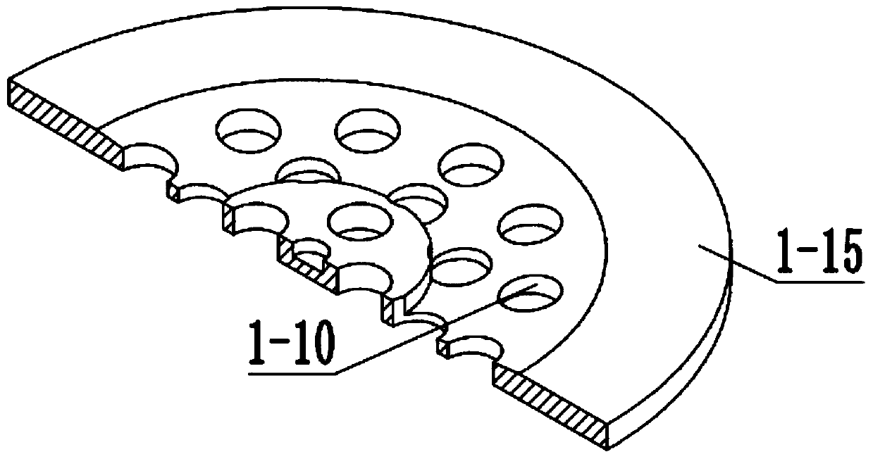
[0034] Combine below Figure 1-18This embodiment, this embodiment will further explain Embodiment 1. The stirring assembly 1 includes a motor 1-1, a motor bracket 1-2, a motor shaft 1-3, a motor shaft bracket 1-4, and a bevel gear I1- 5. Bevel gear Ⅱ1-6, stirring shaft 1-7, stirring shaft support 1-8, end cover 1-9, air inlet 1-10, mixing chamber 1-11, bevel gear Ⅲ1-12, fan blade sleeve 1-13, fan blade 1-14, stirring support 1-15, bristle brush 1-16, screen 1-17, threaded shaft 1-18 and adjustment support 1-19, motor 1-1 and motor support 1- 2-phase connection, the motor bracket 1-2 is connected with the end cover 1-9, the end cover 1-9 is connected with the mixing chamber 1-11, the motor 1-1 is connected with the motor shaft 1-3, and the motor shaft 1-3 Rotationally connected with the motor shaft support 1-4, the motor shaft support 1-4 is connected with the end cover 1-9, the motor shaft 1-3 is connected with the bevel gear I1-5, the bevel gear I1-5 is connected with the be...

specific Embodiment approach 3

[0036] Combine below Figure 1-18 This embodiment, this embodiment will further explain the first embodiment, the screen cleaning assembly 2 includes a pedal 2-1, a shaft I2-2, a telescopic tube 2-3, a telescopic rod 2-4, and a spring I2-5 , Shaft Ⅱ2-6, pedal bottom plate 2-7, pedal shaft 2-8, pedal shaft bracket 2-9, gear Ⅰ2-10, gear Ⅱ2-11, camshaft 2-12, cam 2-13, sprocket Ⅰ2- 14. Chain 2-15, sprocket Ⅱ 2-16, sprocket Ⅱ shaft 2-17, sprocket Ⅱ shaft bracket 2-18, shaft Ⅲ 2-19, shaft Ⅲ bracket 2-20, screen chute 2-21, Outlet 2-22, bottom plate 2-23, traveling wheel support I 2-24, traveling wheel support II 2-25, traveling wheel shaft 2-26 and traveling wheel 2-27, pedal 2-1 is rotationally connected with shaft I 2-2, The shaft I2-2 is connected with the telescopic cylinder 2-3, the telescopic cylinder 2-3 is slidingly connected with the telescopic rod 2-4, the telescopic rod 2-4 is connected with the shaft II2-6, and the shaft II2-6 is connected with the pedal bottom plate 2...


PUM


Abstract

The invention relates to the field of buildings, and more particularly relates to indoor painting equipment. The indoor painting equipment comprises a stirring assembly, a screen clearing assembly anda painting assembly. When indoor painting work is carried out, precipitation and hard blocks are often encountered in a coating, so that painting is uneven, and the coating is coated excessively at one time, so that the coating is scattered and wasted, and wall painting is uneven; the indoor painting equipment solves the above-mentioned problems, the coating is poured into a stirring chamber fromthe inclined surface of an end cover and starts to be stirred after passing through a scrub brush, and the coating is evenly stirred by the scrub brush; through controlling engagement of two bevel gears, fan blades rotate, the fan blades pressurize the coating in the stirring chamber, and painting is started; coating liquid outflow can be triggered once every time a brush tube rotates for one circle, and the coating can be saved to the maximum extent, so that painting is even; and no-triggering can also be set, the coating can be used as a common painting at the moment, water is added to washa screen after painting is finished, the screen can make contact with the scrub brush to brush the screen by depressing a pedal, and it can be ensured that the screen is not blocked.

Description

technical field [0001] The invention relates to the construction field, more specifically to an indoor painting equipment. Background technique [0002] During indoor painting work, it is often encountered that the paint has precipitation and hard lumps leading to uneven painting, and too much paint is applied at one time, which leads to waste of paint and uneven wall painting. The present invention solves the above problems. Contents of the invention [0003] The purpose of the present invention is achieved through the following technical solutions: [0004] An indoor painting equipment includes a stirring assembly, a screen cleaning assembly and a painting assembly, the stirring assembly is connected with the screen cleaning assembly, and the plaster assembly is connected with the stirring assembly. [0005] As a further optimization of this technical solution, the present invention is an indoor painting equipment, the stirring assembly includes a motor, a motor bracket...

Claims


Application Information

Patent Timeline
IPC IPC(8): E04F21/08B01D29/01B01D29/64B01F7/18B08B1/02B08B3/02
CPCE04F21/08B01D29/01B01D29/6415B08B3/022B01F27/90B01F2101/30B08B1/20
Inventor 董贵银林爱仙
Owner 广东穗合建筑装饰有限公司
Features
  • R&D
  • Intellectual Property
  • Life Sciences
  • Materials
  • Tech Scout
  • Unparalleled Data Quality
  • Higher Quality Content
  • 60% Fewer Hallucinations
Learn More