Heat exchanger

A technology of heat exchanger and heat exchange core, which is applied in the field of heat exchange, and can solve the problems of low pressure resistance, difficult heat exchange, and large flow resistance of plate-fin heat exchangers

Active Publication Date: 2020-01-07
ZHEJIANG SANHUA AUTOMOTIVE COMPONENTS CO LTD
View PDF6 Cites 6 Cited by
  • Summary
  • Abstract
  • Description
  • Claims
  • Application Information

AI Technical Summary

Problems solved by technology

[0004] Although the fins can improve the turbulence of the fluid, they also have the problems of large flow resistance and low pressure resistance, which makes it difficult for the plate-fin heat exchanger to be suitable for heat exchange between low-pressure fluid and high-pressure fluid.

Method used


Image

  • Heat exchanger
  • Heat exchanger
  • Heat exchanger

Examples


Embodiment Construction

[0016] Specific embodiments of the present invention will be described below in conjunction with the accompanying drawings.

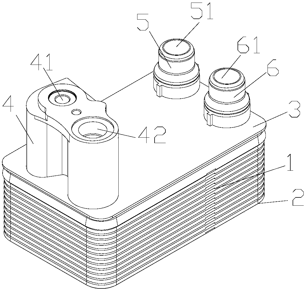
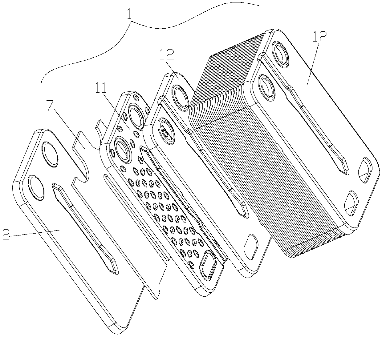
[0017] figure 1 It is a three-dimensional schematic diagram of an embodiment of the heat exchanger of the present invention, figure 2 yes figure 1 The schematic diagram of partial explosion of the bottom plate and the heat exchange core of the shown heat exchanger, as shown in the figure, in this embodiment, the heat exchanger includes a top plate 3, a heat exchange core 1 and a bottom plate 2, and the heat exchange core includes several A first plate 11, a number of second plates 12 and a number of fins 7. In this embodiment, one of the first plates 11 is arranged adjacent to the bottom plate 2, and a fin 7 is arranged between the bottom plate 2 and the first plate 11, and the fin 7 is also a part of the heat exchange core 1. A part, and one of the second plates 12 is adjacent to the top plate 3 .

[0018] A plurality of first plates 11 and a plur...


PUM


Abstract

The invention discloses a heat exchanger. The heat exchanger comprises first sheet bars and second sheet bars, wherein a plurality of convex parts are arranged on the side of a first sheet face of each first sheet bar, fins are arranged between a second sheet face of each first sheet bar and a first sheet face of the second sheet bar adjacent to the first sheet bar, while no fins are arranged between the side, provided with the convex parts, of each first sheet bar and a second sheet face of the second sheet bar adjacent to the first sheet bar, and the height of the convex parts is smaller than that of the fins. According to the heat exchanger, the flow turbulent performance in a first fluid channel is improved through the fins, the flow turbulent performance in a second fluid channel is improved through the structure of the convex parts, thus low-pressure fluid can flow in the first fluid channel, and high-pressure fluid can flow in the second fluid channel.

Description

technical field [0001] The invention relates to the technical field of heat exchange, in particular to a heat exchanger. Background technique [0002] Plate-fin heat exchangers are usually composed of plates and fins. Fins are placed between adjacent two plates to form a fluid channel; multiple such plates are stacked in different ways according to actual needs, and brazed into a whole to form a plate bundle; the plate bundle and the corresponding The plate-fin heat exchanger is formed by assembling the head, connecting pipe, support and other parts. [0003] Compared with the traditional heat exchanger, the plate-fin heat exchanger has a secondary surface and a very compact structure. The disturbance of the fins to the fluid makes the boundary layer of the fluid continuously rupture. At the same time, due to the high thermal conductivity of the plates and fins, The plate-fin heat exchanger has high efficiency. [0004] Although the fins can improve the turbulence of the ...

Claims


Application Information

Patent Timeline
Patent Type & Authority Applications(China)
IPC IPC(8): F28D9/00F28F3/02
CPCF28D9/00F28F3/02F28F2215/08F28D9/0056F28F3/027F28F3/044F28F2275/06F28F9/0251F28D9/005F28F3/025F28D9/0037F28F3/046F28F3/06F28F3/086
Inventor 不公告发明人
Owner ZHEJIANG SANHUA AUTOMOTIVE COMPONENTS CO LTD
Why Eureka
Try Eureka