Electromagnetic mixing device with changeable stirring forms

A form transformation and mixing device technology, applied in mixers, mixer accessories, shaking/oscillating/vibrating mixers, etc., can solve the problems of long cycle and low mixing efficiency, reduce cleaning difficulty, improve mixing efficiency, and reduce the possibility of sexual effect

Inactive Publication Date: 2019-12-31
郑中光
View PDF6 Cites 4 Cited by
  • Summary
  • Abstract
  • Description
  • Claims
  • Application Information

AI Technical Summary

Problems solved by technology

[0002] Liquid mixing devices are widely used in many fields such as agriculture, sewage treatment, chemical production and manufacturing, etc. The purpose is to stir and mix more than two kinds of liquids evenly. The main components of the mixing device in the traditional technology are motor, stirring shaft And the stirring blade, the motor drives the stirring shaft and the stirring blade fixedly connected with it to rotate, so as to perform mixing and stirring. Due to its fixed structure, the disturbance to the liquid is also small, and the cycle is often longer when mixing a large amount of liquid. less efficient

Method used


Image

  • Electromagnetic mixing device with changeable stirring forms
  • Electromagnetic mixing device with changeable stirring forms
  • Electromagnetic mixing device with changeable stirring forms

Examples


Embodiment 1

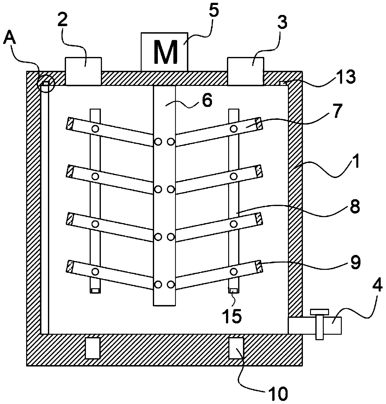
[0022] refer to Figure 1-5 , a mixing device for electromagnetic stirring form conversion, comprising a cylindrical mixing tank 1, a rotating motor 5 is fixedly installed in the middle of the upper end of the mixing tank 1, and a vertical stirring shaft 6 is fixedly connected to the output end of the rotating motor 5 , and the lower end of the stirring shaft 6 runs through the mixing tank 1 and extends to the inner bottom thereof, and the left and right sides of the stirring shaft 6 are symmetrically provided with stirring components;

[0023] The stirring assembly includes a plurality of rotating grooves equidistantly arranged on one side of the stirring shaft 6. In the rotating groove, a pin shaft is used to rotate and connect a stirring blade 7, and a plurality of stirring blades 7 are jointly rotated in a vertical direction and connected with a synchronous rod 8, synchronously The bottom end of the rod 8 is embedded with a permanent magnet 15, and the end of the stirring ...

Embodiment 2

[0033] The difference between this embodiment and the embodiment is that the inner bottom of the mixing tank 1 is evenly embedded with a plurality of vertically arranged electromagnets 14 with the stirring shaft 6 as the center of the circle, and every two adjacent electromagnets 14 The N and S poles of the poles are facing oppositely, the vertical distance between the synchronization rod 8 and the stirring shaft 6 is equal to the vertical distance between the electromagnet 2 14 and the extension line of the stirring shaft 6, and a plurality of electromagnet 2 14 are connected in series with the high-frequency DC power supply .

[0034] According to the working principle of the above-mentioned embodiment 1, the working principle of this embodiment can be easily deduced, so it will not be described in detail, only the difference between the two is described: when the stirring assembly rotates in a circle, when two of them are about to stir When the two electromagnets 14 that ar...


PUM


Abstract

The invention discloses an electromagnetic mixing device with changeable stirring forms. The mixing device includes a cylindrical mixing tank, a rotating electrical machine is fixedly installed at themiddle of the upper end of the mixing tank, the output end of the rotating electrical machine is fixedly connected with a vertically arranged stirring shaft, the lower end of the stirring shaft passes through the mixing tank and extends to the inner bottom of the mixing tank, and the left and right sides of the stirring shaft are symmetrically provided with stirring components; and each stirringcomponent includes a plurality of rotating grooves arranged in one side of the stirring shaft at equal intervals, the interior of each rotating groove is rotatably connected with a stirring blade through a pin shaft, a plurality of stirring blades are rotationally connected with synchronization rods in a vertical direction, and a permanent magnet is embedded into the bottom end of each synchronization rod. The device has the following advantages: from the visual observation, in the process of performing stirring as the whole stirring components rotate, the plurality of stirring blades on the left and right sides of the stirring shaft are rotated in a rotation angle range, so that the turbulence effect during stirring is greatly enhanced, the mixing stirring cycle is shortened, and the mixing efficiency is improved.

Description

technical field [0001] The invention relates to the technical field of mixing devices, in particular to a mixing device with electromagnetic stirring form conversion. Background technique [0002] Liquid mixing devices are widely used in many fields such as agriculture, sewage treatment, chemical production and manufacturing, etc. The purpose is to stir and mix more than two kinds of liquids evenly. The main components of the mixing device in the traditional technology are motor, stirring shaft And the stirring blade, the motor drives the stirring shaft and the stirring blade fixedly connected with it to rotate, so as to perform mixing and stirring. Due to its fixed structure, the disturbance to the liquid is also small, and the cycle is often longer when mixing a large amount of liquid. less efficient. [0003] In order to solve the above problems, we propose a mixing device with electromagnetic stirring and form transformation. Contents of the invention [0004] The pu...

Claims


Application Information

Patent Timeline
Patent Type & Authority Applications(China)
IPC IPC(8): B01F11/00B01F15/00
CPCB01F31/40B01F35/123
Inventor 郑中光
Owner 郑中光
Why Eureka
Try Eureka