Detachable plate shell type heat exchanger

A plate-and-shell heat exchanger technology, applied in the field of detachable plate-and-shell heat exchangers, can solve the problem of reducing the heat-exchange capacity of the plate-and-shell heat exchanger, difficult to restore the heat-exchange effect, and inability to replace the heat-exchange plate bundles and other problems, to achieve the effect of reducing voids, preventing short circuits, and improving heat exchange effect.

Inactive Publication Date: 2012-02-15
SOUTH CHINA UNIV OF TECH
View PDF6 Cites 4 Cited by
  • Summary
  • Abstract
  • Description
  • Claims
  • Application Information

AI Technical Summary

Problems solved by technology

Existing heat exchange plate bundles are used in plate and shell heat exchangers. The medium inlet and outlet structures are complex and difficult to process and manufacture. The structure is poor in compactness and the sealing performance is not high.
The heat exchange plate bundles used are all assembled from plates of the same length and width. The formed plate bundles are in a rectangular shape. When placed in a circular cylinder, there will be a large number of gaps in the shell side, and the medium flows directly through the gaps. Without heat exchange, the heat exchange capacity of the plate and shell heat exchanger is greatly reduced.
In addition, the commonly used plate and shell heat exchangers are mostly installed in the form of full welding. The heat exchange plate bundle and the tube sheet of this structure cannot be separated after welding. When the heat exchange plate bundle is scaled or blocked, it is difficult to clean. , and it is difficult to restore the heat exchange effect; when the heat exchange plate bundle is damaged, the damaged heat exchange plate bundle cannot be replaced, and the tube sheets at both ends and the entire heat exchange plate bundle must be replaced at the same time

Method used


Image

  • Detachable plate shell type heat exchanger
  • Detachable plate shell type heat exchanger
  • Detachable plate shell type heat exchanger

Examples


Embodiment 1

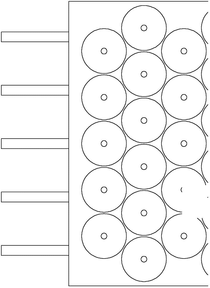
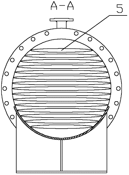
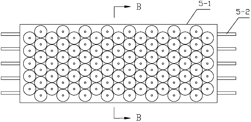
[0042] Such as figure 1 As shown, a detachable plate and shell heat exchanger includes a shell 4, a tube box 1, an inner tube sheet 6, an outer tube sheet 7, and a heat exchange plate bundle installed in the shell. The shell 4 has two Each end is provided with a pipe box 1. The inner tube plate 6 and the outer tube plate 7 are stacked together, located between the tube box 1 and the shell 4, and fixed together by two flanges 2 and bolts, and a gasket is installed between the two flanges 2 slice 9. A plate bundle composed of parallel plates 5 is arranged between the tube plates on both sides, and the plates 5 are arranged at equal intervals, and its two ends are fixed on the tube plates on both sides through plate tubes 5-2, and the plates 5 and The pipe box 1 is connected, and the shell 4 is provided with shell-side inlet and outlet connecting pipes 3-1 and 3-2, and the pipe box 1 is provided with board-side inlet and outlet connecting pipes 8-1 and 8-2. Such as figure 2 ...


PUM


Abstract

The invention discloses a detachable plate shell type heat exchanger. Pipe boxes are arranged at the two ends of a shell, two pipe plates are arranged between the pipe boxes and the shell and fixed together by flanges, a plate bundle consisting of parallel plate sheets is arranged between the pipe plates on the two sides, the two ends of each plate sheet are fixed on the two pipe plates on the two sides by plate pipes and communicated with the pipe boxes, a shell pass inlet and a shell pass outlet are formed on the shell, plate pass inlets and plate pass outlets are formed on the pipe boxes, the plate sheets comprise flow passage cavities and the plate pipes, the sections of the flow passage cavities are oblate, honeycomb structures are formed in the flow passage cavities, the two ends ofeach flow passage cavity are welded with the plate pipes which are communicated with the flow passage cavity, the plate pipes are inserted into the pipe holes of the pipe plates, and the outer surfaces of the plate pipes and the pipe holes are sealed by internal pipe plate compacting sealing rings and external pipe plate compacting sealing rings; the plate sheets comprise long plate sheets and short plate sheets, so that a shell pass has a multi-shell pass structure; and flow passages among the plate sheets are separated and supported by pull rods. The detachable plate shell type heat exchanger has high heat exchanging performance and is convenient to disassemble, wash, replace and assemble.

Description

technical field [0001] The invention belongs to the field of heat exchange equipment, and relates to a detachable plate-shell heat exchanger using laser-welded honeycomb plates as heat exchange elements. Background technique [0002] Heat exchanger is a heat exchange equipment widely used in the national economy and industrial production. Its performance and enhanced heat transfer effect have an important impact on energy saving and consumption reduction in the process industry. As a new type of high-efficiency heat exchange equipment, the plate and shell heat exchanger uses heat exchange plates instead of traditional heat exchange tubes as heat exchange elements. The plate heat exchanger has a large heat transfer area, high heat transfer efficiency, compact structure, and low weight. It has the advantages of being light, and at the same time inherits the advantages of high pressure and high temperature resistance, good sealing performance, safety and reliability of the shel...

Claims


Application Information

Patent Timeline
Patent Type & Authority Applications(China)
IPC IPC(8): F28D9/00F28F3/08F28F13/12
Inventor 江楠陈武滨
Owner SOUTH CHINA UNIV OF TECH
Why Eureka
Try Eureka