Radiator

A technology of radiator and heat dissipation fins, applied in the direction of instruments, instrument cooling, electric solid devices, etc., can solve problems such as the reduction of heat exchange effect

Inactive Publication Date: 2007-12-12
FU ZHUN PRECISION IND SHENZHEN +1
View PDF0 Cites 4 Cited by
  • Summary
  • Abstract
  • Description
  • Claims
  • Application Information

AI Technical Summary

Problems solved by technology

If the cooling fins with a flat plate structure are used, when the fan airflow flows through the cooling fins, due to the influence of viscous force, the contact part between the surface...

Method used


Image

  • Radiator
  • Radiator
  • Radiator

Examples


Embodiment Construction

[0011] Further description will be made below in conjunction with the embodiments with reference to the accompanying drawings.

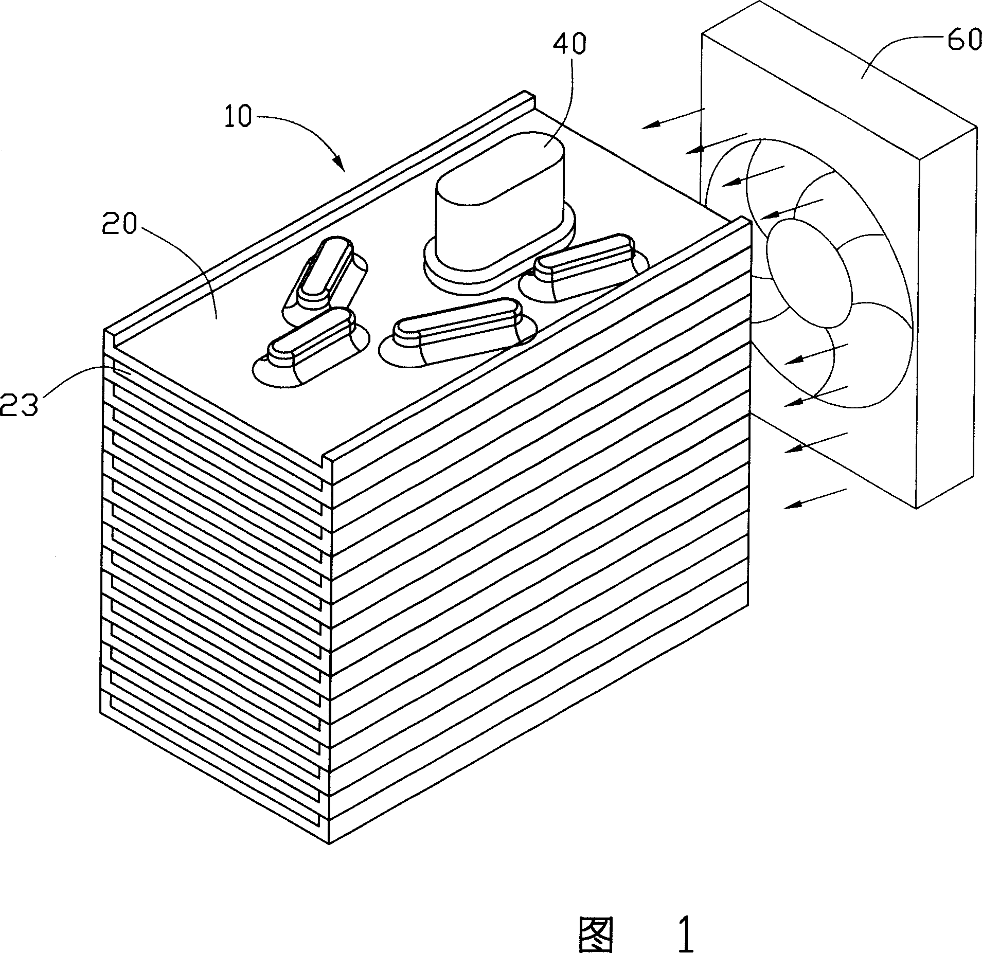
[0012] As shown in Figure 1, the radiator includes a heat dissipation fin set 10, a heat pipe 40 passing through the heat dissipation fin set 10, and a heat dissipation fan placed at one end of the heat dissipation fin set 10 for providing forced airflow 60. The airflow generated by the fan 60 can flow into the heat dissipation fin set 10 along the direction indicated by the arrow in the figure, so as to exchange heat with the heat dissipation fin set 10 to remove heat.

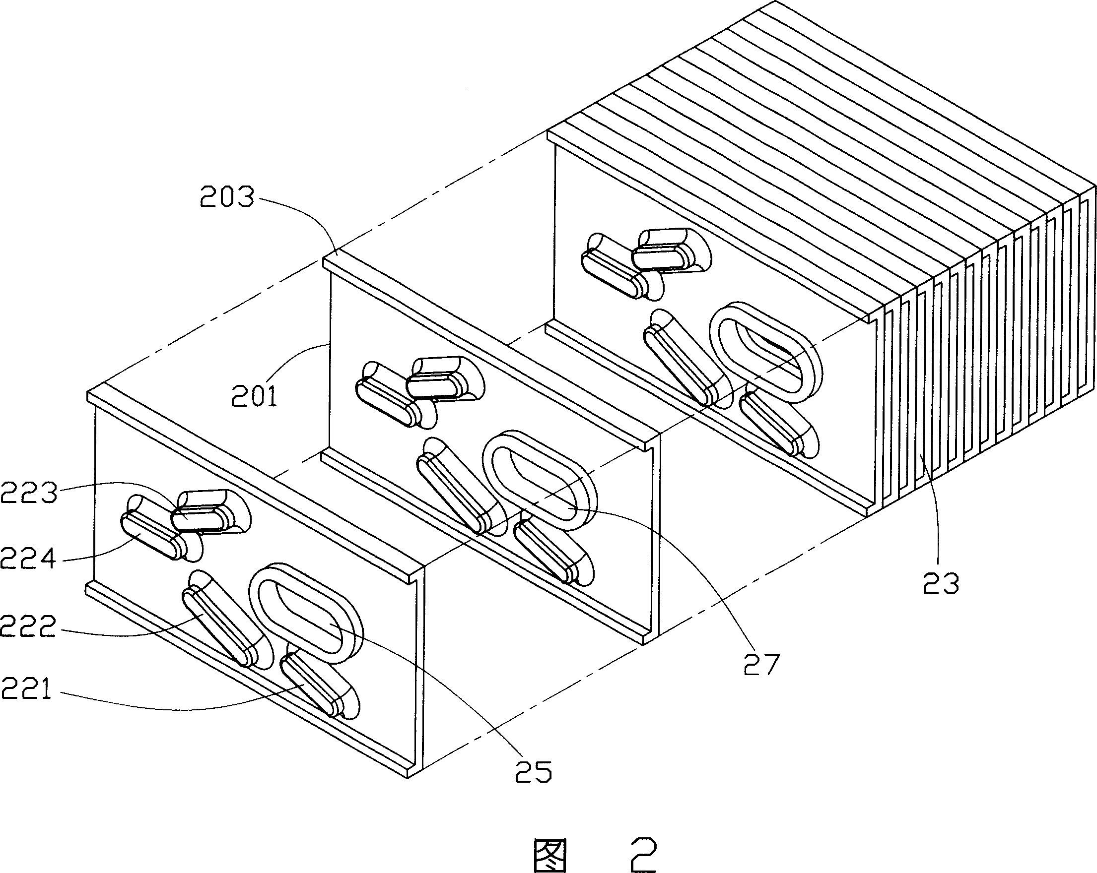
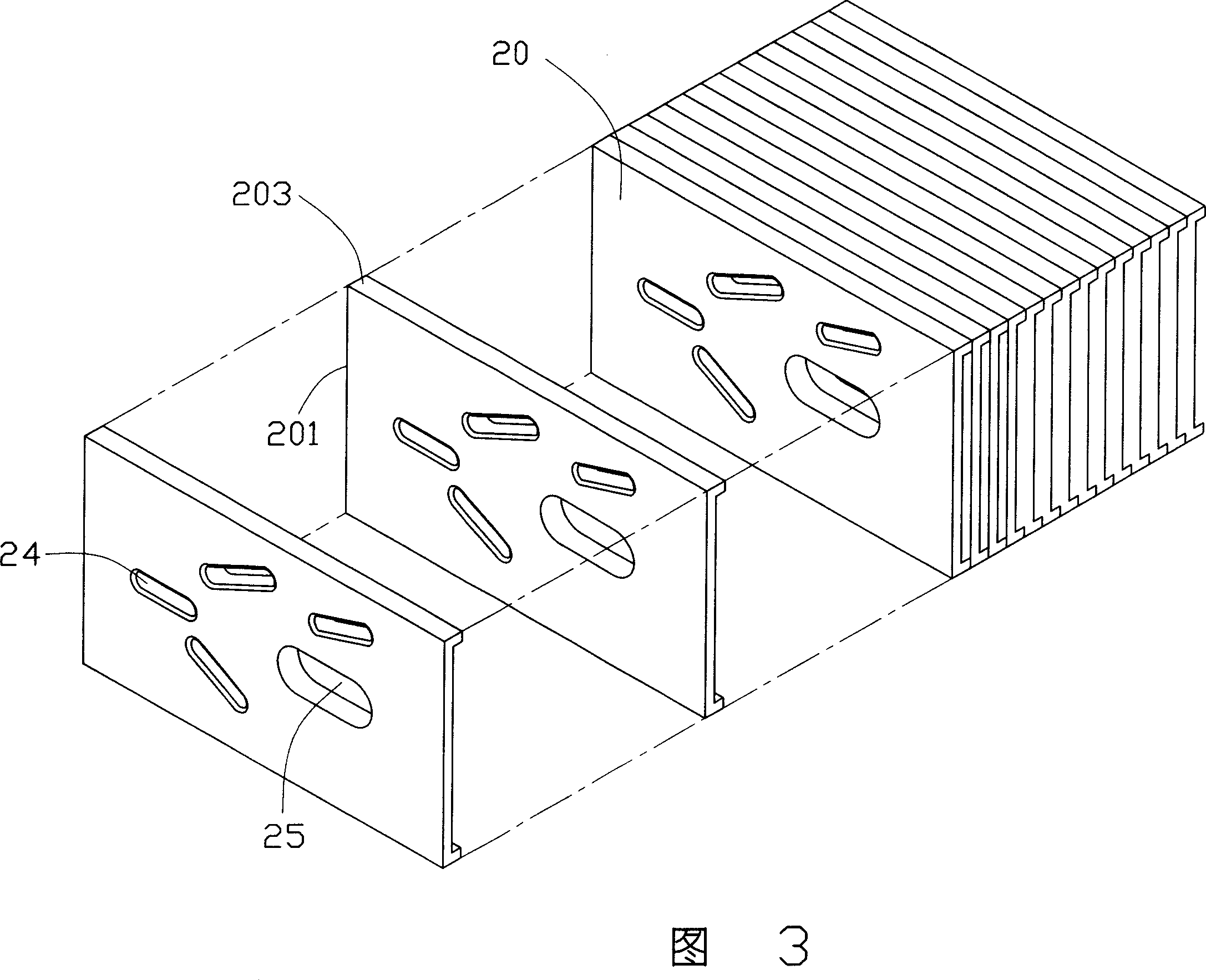
[0013] Please refer to FIGS. 2 to 4 at the same time. The heat dissipation fin group 10 includes a number of fins 20 arranged parallel to each other. Each fin 20 includes a body 201 and flanges 203 formed at both ends of the body 201. The folded edges 203 of the fins abut against each other, thereby forming a flow channel 23 extending along the length direction of the folded edges ...


PUM


Abstract

A kind of radiator includes several radiating fins which are set parallel with each other and hot pipe which is set through the radiating fins, flow channel for air flow is formed between adjacent radiating fins, a through hole for the hot pipe is set on every radiating fin, several heaves are set around the through hole on the radiating fin, said several heaves are arranged to shrinkage type. Said heaves can increase radiating area of radiating fin, at the same time it can guide flow and change flow field of air flow, increase burbling effect of radiating fin, radiating efficiency can be increased.

Description

technical field [0001] The invention relates to a heat sink, in particular to a heat sink suitable for heat dissipation of electronic components. Background technique [0002] With the continuous improvement of the power of electronic components such as the central processing unit (CPU), the problem of heat dissipation is more and more paid attention to by people, especially in computers. In order to efficiently remove the heat generated by the system in a limited space, the current industry mainly adopts a combination of heat dissipation fins, heat pipes and heat dissipation fans for heat dissipation. The fan is mainly to provide flowing air, the heat pipe is mainly for long-distance heat transfer, and the task of the cooling fin is to transfer the heat brought by the heat pipe to the external environment through the flowing air generated by the fan drive. It can be seen that in a fixed volume space, whether the heat generated by the electronic components can be evacuated ...

Claims


Application Information

Patent Timeline
IPC IPC(8): H05K7/20H01L23/427G06F1/20G12B15/00
Inventor 黄清白李志坚
Owner FU ZHUN PRECISION IND SHENZHEN
Why Eureka
Try Eureka