
A Measuring Method of Shaking Amount of Optical Axis of Zoom Camera

A measurement method and zoom camera technology, which are applied in the testing of machine/structural components, measurement devices, optical axis determination, etc., can solve the problems of complex measurement process, long time consumption, and high cost of measurement equipment, and ensure measurement accuracy and convenient operation. , the effect of simple structure

Active Publication Date: 2021-07-30
西安中科立德红外科技有限公司
View PDF0 Cites 0 Cited by
  • Summary
  • Abstract
  • Description
  • Claims
  • Application Information

AI Technical Summary

Problems solved by technology

[0006] The main purpose of the present invention is to solve the technical problems of high cost, complicated and time-consuming measurement process caused by many measuring equipments involved in the measurement method of optical axis shake of zoom camera in the prior art, and to provide a measurement of optical axis shake of zoom camera method

Method used


Image

  • A Measuring Method of Shaking Amount of Optical Axis of Zoom Camera

Examples


Embodiment 1

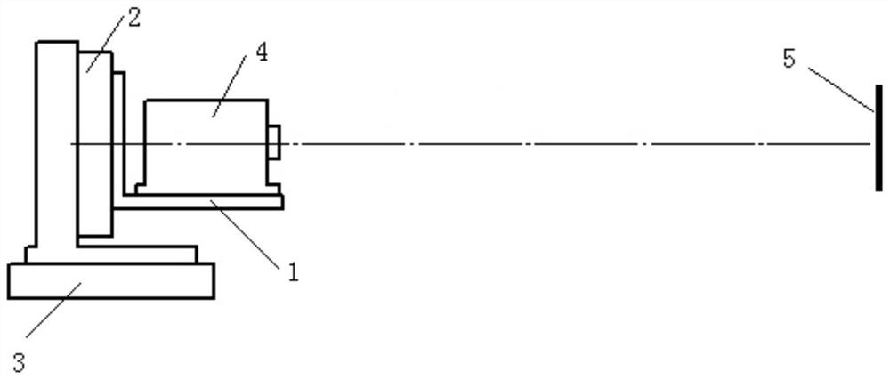
[0028] Such as figure 1 , a method for measuring the optical axis shake of a zoom camera, the specific steps are as follows:

[0029] Step 1, select the corner of the building as the target 5, fix the vertical indexing table 2 on the two-dimensional adjustment frame 3, the table top of the vertical indexing table 2 is vertical, and fix the zoom camera 4 on the vertical indexing table 2 On the camera mount 1 on the table, make the rotating shaft of the vertical indexing table 2 parallel to the optical axis of the zoom camera 4, and the parallelism is one-third of the field of view angle at the preset focal length, and then adjust the zoom camera to the preset focal length;

[0030] Step 2, adjust the optical axis of the zoom camera 4 through the two-dimensional adjustment frame 3, so that the center of the optical axis is aligned with the corner of the building, and record the first lateral miss distance x from the corner of the building to the center of the zoom camera 4 0 a...

Embodiment 2

[0035] Such as figure 1 , a method for measuring the optical axis shake of a zoom camera, the specific steps are as follows:

[0036] Step 1, select the spire as the target 5, fix the vertical indexing table 2 on the two-dimensional adjustment frame 3, the table top of the vertical indexing table 2 is vertical, and fix the zoom camera 4 on the vertical indexing table 2 On the camera mount 1 on the table, make the rotating shaft of the vertical indexing table 2 parallel to the optical axis of the zoom camera 4, and the parallelism is one-third of the angle of view to be measured, and then adjust the zoom camera to the preset focal length;

[0037] Step 2, adjust the optical axis of the zoom camera 4 through the two-dimensional adjustment frame 3, so that the center of the optical axis is aligned with the spire, and record the first lateral miss distance x from the spire to the center of the zoom camera 4 0 and the first longitudinal miss amount y 0 ;

[0038] Step 3: Rotate ...


PUM


Abstract

The invention belongs to a parameter measurement method of a zoom camera. In order to solve the technical problems of high cost caused by many measuring equipments involved in the measurement method of the optical axis shake of the zoom camera in the prior art, as well as the complicated and time-consuming measurement process, a zoom camera optical axis is provided. The method for measuring the shaking amount is as follows: select a target, fix the zoom camera, adjust the zoom camera to a preset focal length; adjust the zoom camera so that the center of the optical axis of the zoom camera is aligned with the center of the target, and record the center of the target to the zoom camera The first lateral miss amount at the center x 0 and the first longitudinal miss amount y 0 ;Rotate the zoom camera at preset angle intervals, record the lateral miss distance x from the center of the target to the center of the zoom camera n and the longitudinal off-target amount y n ; Carry out Fourier transform on the obtained horizontal miss amount and longitudinal miss amount respectively, and obtain the second-order component x a and y a , what is calculated is the amount of optical axis shake of the zoom camera at the preset focal length.

Description

technical field [0001] The invention belongs to a parameter measurement method of a zoom camera, and in particular relates to a measurement method of an optical axis shaking amount of a zoom camera. Background technique [0002] The zoom optical system is generally composed of three parts: fixed group, zoom group and compensation group. The zoom group and compensation group move along the guide rail or cam according to specific rules to achieve continuous change of focal length and image plane stability. Zoom group and compensation group When moving along the guide rail or cam, there is a certain gap between the zoom group and compensation group and the guide rail and cam due to the processing and assembly errors of the guide rail and cam. The gap is inevitable, generally less than 0.01mm-0.02mm. When the installation direction of the zoom camera and the direction of gravity change, even if the focal length does not change, the optical axis will still change, and in the phot...

Claims


Application Information

Patent Timeline
Patent Type & Authority Patents(China)
IPC IPC(8): G01M11/04G01M11/02
CPCG01M11/0221G01M11/04
Inventor 王海赵胜强马仁旺
Owner 西安中科立德红外科技有限公司
Learn More