
Optical fiber connector

A fiber optic connector and connector technology, applied in light guides, optics, instruments, etc., can solve the problems of dust entering the connector housing and affecting the normal use of fiber optic connectors, so as to ensure the transmission efficiency of optical signals and improve dust prevention Effect, structure design simple effect

Inactive Publication Date: 2020-01-07
CHINA AVIATION OPTICAL-ELECTRICAL TECH CO LTD
View PDF6 Cites 0 Cited by
  • Summary
  • Abstract
  • Description
  • Claims
  • Application Information

AI Technical Summary

Problems solved by technology

[0004] The purpose of the present invention is to provide an optical fiber connector to solve the technical problem in the prior art that dust easily enters the connector housing from the rear of the contact module and affects the normal use of the optical fiber connector

Method used


Image

  • Optical fiber connector
  • Optical fiber connector
  • Optical fiber connector

Examples


specific Embodiment 1

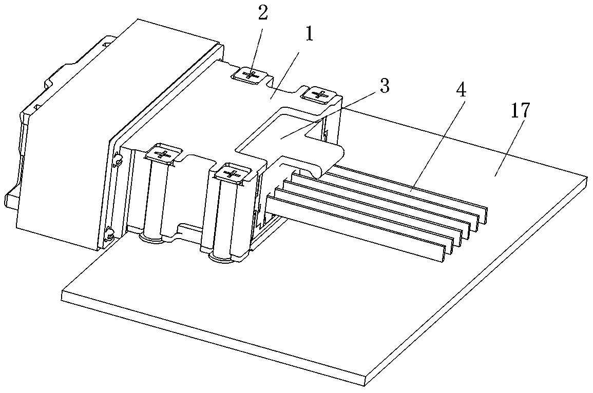
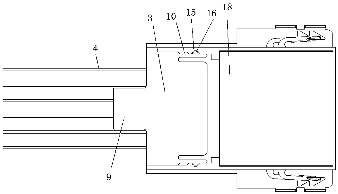
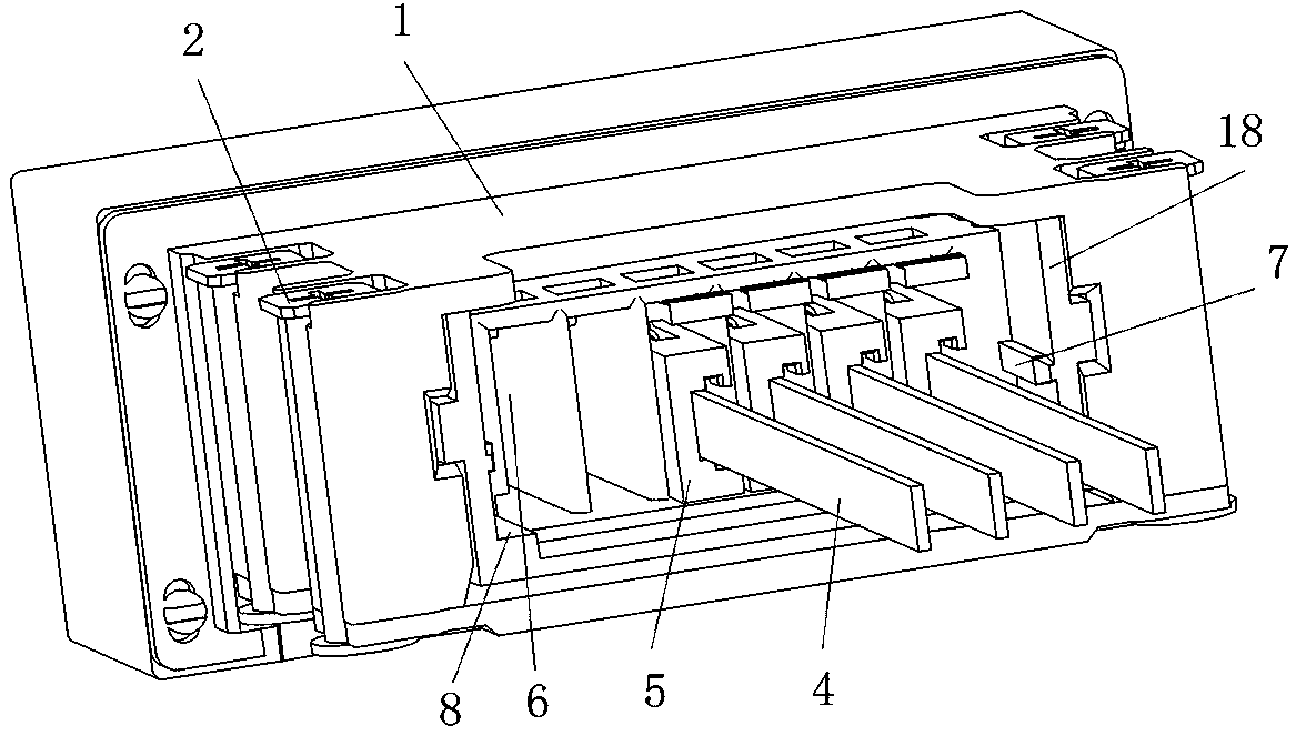
[0034] like figure 1 and figure 2 As shown, the optical fiber connector includes a connector housing, the front end of which is a plug end, and the rear end is an outlet end. The connector housing includes an outer housing 1 and an inner housing 18. The optical fiber connector is fixedly assembled on the fixing plate 17 through the cooperation of the outer casing 1 and the screw 2 . like image 3 As shown, the inner casing 18 is provided with an insertion hole 6 , and a plurality of contact modules 5 are inserted into the insertion hole 6 from the rear to the front, and the rear ends of each contact module 5 are connected with the optical cable 4 . In order to prevent dust from entering the inner casing 18 from the contact module 5 and affecting the transmission of the optical signal, the rear end of the inner casing 18 is fixedly equipped with a rear dust cover 3 .

[0035] In this embodiment, the rear dust cover 3 is snap-fitted on the inner casing 18, and the fixing met...

specific Embodiment 2

[0046] like Figure 5 As shown in the figure, the difference between this embodiment and the specific embodiment 1 is that the rear dustproof plate of the rear dust cover 3 is provided with an avoidance gap 19, and the avoidance gap 19 is not provided with dustproof teeth. The two adjacent optical cables 4 enter the inner casing 18 in the interval, and the dustproof effect is not very good.

specific Embodiment 3

[0048] The difference between this embodiment and the specific embodiment 1 is that the rear dust cover is inserted into the inner casing from top to bottom, so that the rear dust cover can be snap-fitted into the inner casing, and the upper and lower limits can be realized by snap-fitting. At this time, a guide protrusion extending in the up-down direction can be arranged on the inner wall of the inner casing, and a guide groove extending in the up-down direction can be arranged on the rear dust cover. To ensure that the rear dust cover is fixedly assembled in the inner casing.


PUM


Abstract

The invention relates to an optical fiber connector. The optical fiber connector comprises a connector shell, a contact element module and a rear dustproof cover, wherein the front end of the connector shell is an insertion connection end, and the rear end of the connector shell is a cable outlet end; the contact element module is fixedly inserted in the connector shell, and an optical cable is led out from the rear end of the contact element module; the rear dustproof cover is fixedly assembled at the cable outlet end of the connector shell and covers the contact element module; and the reardustproof cover is provided with an avoidance gap to avoid the optical cable. The dustproof cover is arranged at the cable outlet end of the connector shell to cover the contact element module in theconnector shell, so that the amount of dust entering the connector shell through the cable outlet end is reduced, the contact element module is prevented from being polluted, and the optical signal transmission efficiency of the contact element module is ensured; and moreover, the avoidance gap in the rear dustproof cover can avoid the optical cable connected with the contact element module, so that smooth leading-out of the optical cable is guaranteed.

Description

technical field [0001] The present invention relates to an optical fiber connector. Background technique [0002] Optical signal transmission engineering plays a very important role in the development of communication and information technology, and optical fiber connectors, as the basic components of optical signal transmission, are even more indispensable. The Chinese invention patent with the authorization announcement number CN105242156B discloses a connector assembly. The plug-in end of the connector assembly is provided with a dust cover to prevent dust from entering the interior of the corresponding connector. Each connector is fixedly equipped with a contactor. Each contact module is connected with an optical cable, the optical cable is drawn out from the outlet end of the connector, and the rear of the contact module is exposed. [0003] Since fiber optic connectors are generally used in cabinets, and the cabinets usually use air-cooled heat dissipation, under air-...

Claims


Application Information

Patent Timeline
Patent Type & Authority Applications(China)
IPC IPC(8): G02B6/38
CPCG02B6/3849
Inventor 田建伟郑伟涛管鹏举石晓强
Owner CHINA AVIATION OPTICAL-ELECTRICAL TECH CO LTD
Learn More