Protection device for high-low-voltage cabinet

A technology for protection devices and high and low voltage cabinets, applied in substation/distribution device enclosures, substation/switchgear cooling/ventilation, substation/switch layout details, etc. , to achieve the effect of prolonging the service life, improving the convenience and improving the safety

Inactive Publication Date: 2020-01-07
江苏中顺电气有限公司
View PDF5 Cites 0 Cited by
  • Summary
  • Abstract
  • Description
  • Claims
  • Application Information

AI Technical Summary

Problems solved by technology

[0002] At present, the safety protection measures of the high and low voltage cabinet protection devices on the market are slightly single. Many manufacturers' high and low voltage cabinets are operated outdoors. Not only are they exposed to sunlight to generate high temperatures, but they also generate heat during operation. The temperature inside the electric cabinet will reach above 60°C. If the necessary safety precautions are not taken at this time, the power distribution cabinet will exceed the specified ambient temperature, which will cause the components in the cabinet to overheat and malfunction. As we all know, the power distribution cabinet in the basement and other humid working environments will affect the terminals, wires and wiring rows in the substation terminal box to mildew and metal oxidation accidents, and in severe cases, it will cause accidents such as short circuit, insulator breakdown or even burning. , which leads to great safety hazards, so it is very important to be able to reliably and effectively dehumidify the high and low voltage cabinets. With the increase in fire and electricity consumption in modern homes, the frequency of fires is getting higher and higher. Once a family fire occurs Unfavorable factors such as untimely rescue, lack of fire extinguishing equipment, panic of the people present, and slow escape are likely to occur, which will eventually lead to heavy loss of life and property. Therefore, it is of practical significance to discuss fire alarms and reduce fire losses.

Method used


Image

  • Protection device for high-low-voltage cabinet
  • Protection device for high-low-voltage cabinet

Examples


Embodiment Construction

[0014] The following will clearly and completely describe the technical solutions in the embodiments of the present invention with reference to the accompanying drawings in the embodiments of the present invention. Obviously, the described embodiments are only some, not all, embodiments of the present invention. Based on the embodiments of the present invention, all other embodiments obtained by persons of ordinary skill in the art without making creative efforts belong to the protection scope of the present invention.

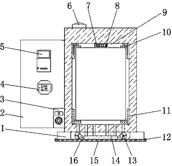
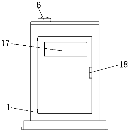
[0015] see Figure 1-2 , an embodiment provided by the present invention: a protective device for high and low voltage cabinets, including a protective cabinet main body 1, a door body 2, a dehumidifier 3, a fire alarm 6, and a heat dissipation cavity 14, and the bottom of the protective cabinet main body 1 The central position is provided with a cooling cavity 14, and the bottom end of the cooling cavity 14 is equipped with a cooling disc 16, and the cooling ...


PUM


Abstract

The invention discloses a protection device for a high-low-voltage cabinet. The protection device comprises a protection cabinet main body, a door body, a dehumidifier, a fire alarm and a heat dissipation cavity; a heat dissipation cavity is formed at the center of the bottom end of the protection cabinet main body; a heat dissipation disc is mounted at the bottom end in the heat dissipation cavity; heat dissipation fans are arranged in the heat dissipation cavities at the two sides of the heat dissipation disc; a fireproof barrier layer is arranged at the bottom end of the protection cabinetmain body; folding screw holes are hinged to the two side walls of the fireproof blocking layer, a clamping cavity is formed in the center of the interior of the protection cabinet body, a fixing buckle is arranged on the inner side wall of the clamping cavity, lifting buckles are installed at the two ends of the fixing buckle, and a temperature sensor is fixed to the center of the top end of theclamping cavity. The safety of the protection device in use is improved, the convenience degree of the high-low-voltage cabinet in installation is improved, and the service life of the protection device is prolonged.

Description

technical field [0001] The invention relates to the technical field of cabinet protection devices, in particular to a high and low voltage cabinet protection device. Background technique [0002] At present, the safety protection measures of the high and low voltage cabinet protection devices on the market are slightly single. Many manufacturers' high and low voltage cabinets are operated outdoors. Not only are they exposed to sunlight to generate high temperatures, but they also generate heat during operation. The temperature inside the electric cabinet will reach above 60°C. If the necessary safety precautions are not taken at this time, the power distribution cabinet will exceed the specified ambient temperature, which will cause the components in the cabinet to overheat and malfunction. As we all know, the power distribution cabinet in the basement and other humid working environments will affect the terminals, wires and wiring rows in the substation terminal box to mild...

Claims


Application Information

Patent Timeline
Patent Type & Authority Applications(China)
IPC IPC(8): H02B1/30H02B1/56H02B1/28
CPCH02B1/28H02B1/30H02B1/565
Inventor 刘洋
Owner 江苏中顺电气有限公司
Why Eureka
Try Eureka