Neurological examination lifting device

A lifting device and neurology technology, applied in the field of neurology examination lifting devices, can solve the problems of troublesome treatment process of patients, inconvenient clinical use, fatigue of medical staff and patients, etc., and achieves suitable promotion and use, reasonable design and convenient operation. Effect

Inactive Publication Date: 2020-01-10
张长伟
View PDF5 Cites 0 Cited by
  • Summary
  • Abstract
  • Description
  • Claims
  • Application Information

AI Technical Summary

Problems solved by technology

[0002] In the course of their work, medical staff in the Department of Neurology often encounter patients with unexpected situations, and patients are often faced with unstable situations. However, in the past routine examination process, there are many unreasonable design of the examination bed. There are many places that may cause harm to patients, and there are many unsafe places, which will bring unnecessary troubles to the treatment process of patients, and are not conducive to the smooth development of the work of medical staff. Or patients who are not sensitive to local nerve stimulation, the medical staff should check the affected area, and sometimes the patient needs to raise the upper or lower limbs, but most patients have inconvenient limb movements and cannot move freely, and medical staff are required to cooperate, so that medical staff and patients I feel very tired, and it is not convenient to check the operation
[0003] Chinese patent (publication number: CN209347538U) discloses a lifting device for neurologist examination, including two fixing devices, the fixing device includes a fixing frame, a magnet is bonded to one side of the inner wall of the fixing frame, and the fixing The top of the frame is fixed with a manual telescopic rod by bolts, and the top of the manual telescopic rod is welded with a fixed column, and a fixed plate is fixed on one side of the outer wall of the fixed column by bolts. Pulling groove, and a pulling rod is plugged into the pulling groove, one end of the pulling rod is welded on one side of the outer wall of the fixing column, a fixing hole is opened on the top of the fixing plate, and the fixing hole is connected with the pulling groove , the device can achieve the effect of lifting, but the distance between the two supporting devices is fixed and cannot be adjusted, which is inconvenient in clinical use, so the device needs to be improved

Method used


Image

  • Neurological examination lifting device
  • Neurological examination lifting device
  • Neurological examination lifting device

Examples


Embodiment 1

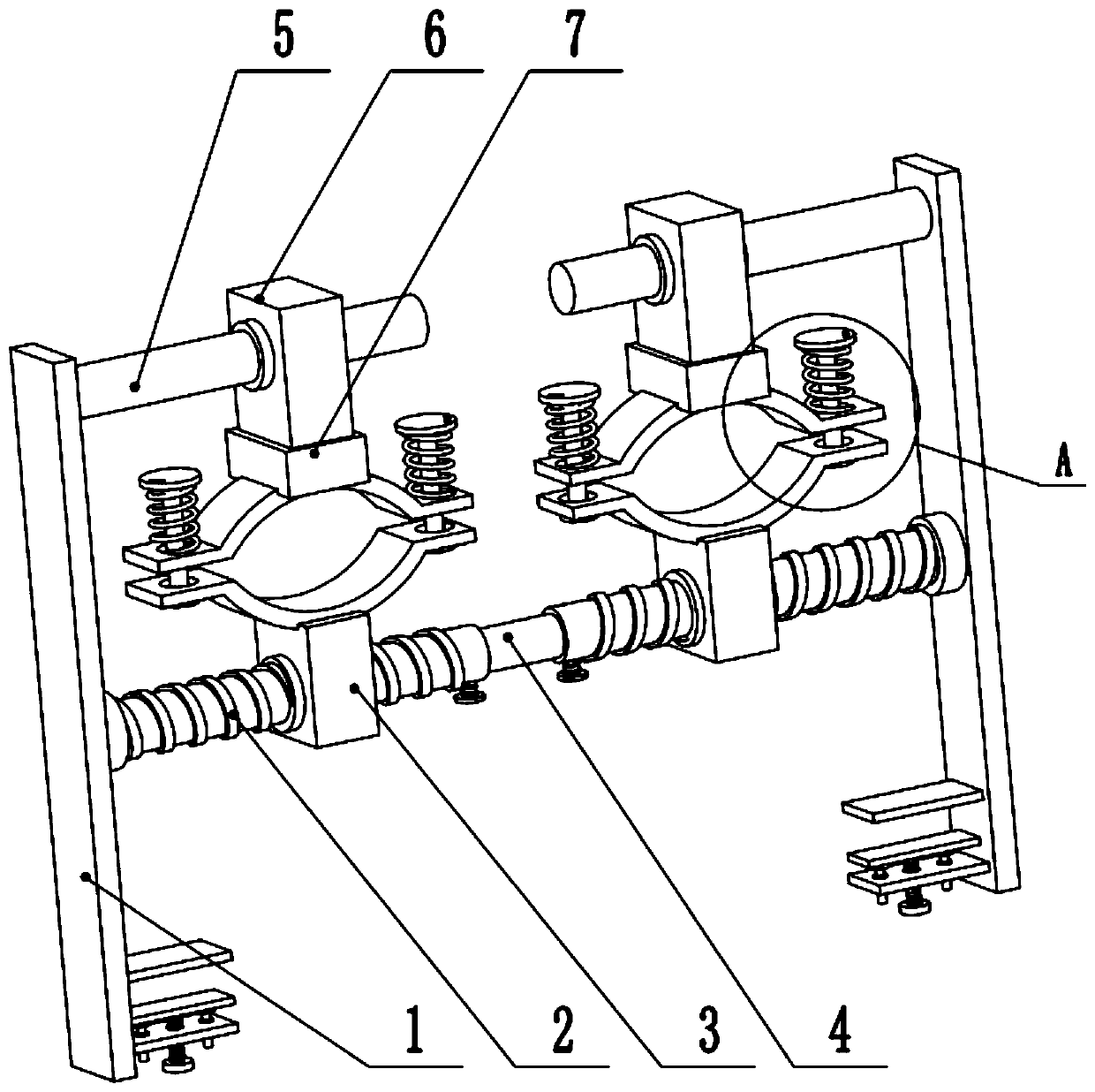
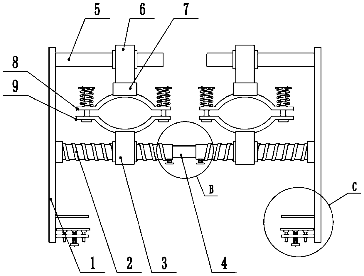
[0026] see Figure 1-6 , a lifting device for neurology examination, comprising a fixed plate 1, the upper end of the fixed plate 1 is provided with a first guide rod 5, the first guide rod 5 is slidably connected to a slider 6, and the lower end of the slider 6 is slidably connected to a sliding seat 7, and the sliding The lower part of the seat 7 is connected to the upper clamping plate 8, the middle part of the fixed plate 1 is rotated and connected to the screw rod 2, the two screw rods 2 are slidably connected to the sliding rod 4 at one end close to the center of the device, and the two screw rods 2 are close to the center of the device One end is threadedly connected to the first tightening screw 14, and the screw rod 2 and the sliding rod 4 can be locked by the first tightening screw 14, so as to realize the fixing of the screw rod 2 and the sliding rod 4. The middle thread of the screw rod 2 Connect the nut 3, the upper part of the nut 3 is connected to the lower clam...

Embodiment 2

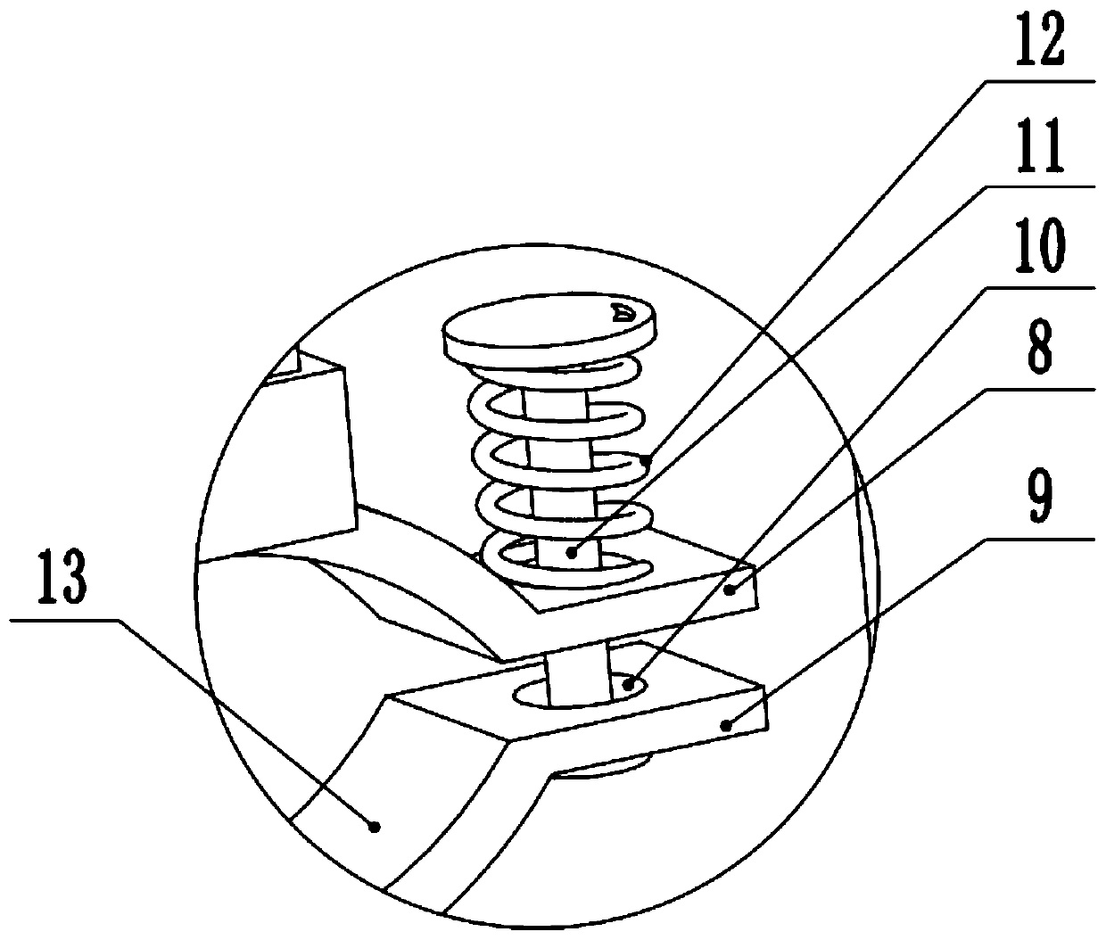
[0029] see image 3 , The other content of this embodiment is the same as that of Embodiment 1, except that: the opposite surfaces of the upper clamping plate 8 and the lower clamping plate 9 are provided with gaskets 13 . Since the device needs to fix the patient's hands or feet through the upper clamping plate 8 and the lower clamping plate 9, the upper clamping plate 8 and the lower clamping plate 9 are directly in contact with the patient. A liner 13 is arranged on the surface, and the liner 13 adopts flexible materials such as sponge to play a certain buffering effect and improve the user experience of the patient.

[0030] During the implementation of the present invention, when in use, the fixing plate 1 is first pulled to both sides, the sliding rod 4 is continuously drawn out from the screw mandrel 2, the fixing plate 1 is placed on the left and right sides of the hospital bed 20, and the first clamping plate 15 and the movable plate 16 are placed on the upper and lo...


PUM


Abstract

The invention relates to the technical field of medical instruments. The invention discloses a neurological examination lifting device. The lifting device comprises fixed plates; a first guide rod isarranged at the upper end of each fixed plate; each first guide rod is slidably connected with a sliding block; a sliding seat is slidably connected to the lower end of each sliding block; the lower part of each sliding seat is connected with an upper clamping plate; the middle part of each fixed plate is rotationally connected with a screw rod; the ends, close to the center of the device, of thetwo screw rods are slidably connected with a sliding rod; the middle of each lead screw is in threaded connection with a nut; the upper portion of each nut is connected with a lower clamping plate; through holes are respectively formed in the left ends and the right ends of each upper clamping plate and each lower clamping plate; the middle of each group of the through holes is connected with a second guide rod in a penetrating mode; a first clamping plate and a second clamping plate are arranged on the lower portion of each fixed plate; and the middle of each second clamping plate is in threaded connection with a second press screw. According to the neurological examination lifting device, the screw rods are arranged on two sides of the device, and the position in the left-right directionof the upper clamping plates and the lower clamping plates can be automatically adjusted through transmission structures of the lead screws and the nuts.

Description

technical field [0001] The invention relates to the technical field of medical devices, in particular to a lifting device for neurological examination. Background technique [0002] In the course of their work, medical staff in the Department of Neurology often encounter patients with unexpected situations, and patients are often faced with unstable situations. However, in the past routine examination process, there are many unreasonable design of the examination bed. There are many places that may cause harm to patients, and there are many unsafe places, which will bring unnecessary troubles to the treatment process of patients, and are not conducive to the smooth development of the work of medical staff. Or patients who are not sensitive to local nerve stimulation, the medical staff should check the affected area, and sometimes the patient needs to raise the upper or lower limbs, but most patients have inconvenient limb movements and cannot move freely, and medical staff a...

Claims


Application Information

Patent Timeline
Patent Type & Authority Applications(China)
IPC IPC(8): A61G13/12
CPCA61G13/1235A61G13/1285
Inventor 张长伟
Owner 张长伟
Why Eureka
Try Eureka