Limiting and fixing device for bending machine

A technology of limit fixation and limit device is applied in the field of bending machine manufacturing to achieve the effect of simple structure

Pending Publication Date: 2020-01-10
南通福马重型机床制造有限公司
View PDF0 Cites 5 Cited by
  • Summary
  • Abstract
  • Description
  • Claims
  • Application Information

AI Technical Summary

Problems solved by technology

[0003] However, there is no limit fixing device installed on the bending machine at present, so when bending, it is necessary to manually stabilize the plate before bending, which is easy to cause installation accidents

Method used


Image

  • Limiting and fixing device for bending machine
  • Limiting and fixing device for bending machine
  • Limiting and fixing device for bending machine

Examples


Embodiment Construction

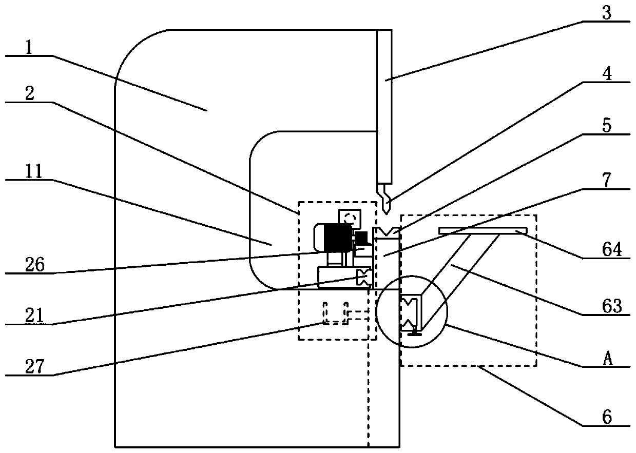
[0023] see Figure 1-Figure 6 As shown, the technical solution adopted in this specific embodiment is: it includes a shearing machine main body 1, a limit device 2, a moving plate 3, an upper mold 4, a lower mold 5, a supporting device 6, and a workbench 7. The front middle position of the shearing machine main body 1 is provided with a working area 11, and the moving plate 3 is installed above the front portion of the shearing machine main body 1, and the moving plate 3 is connected with the hydraulic device of the shearing machine main body 1, so The upper mold 4 is connected below the moving plate 3, the workbench 7 is installed on one side of the work area 11, the lower mold 5 is installed directly above the workbench 7, and the supporting device 6 Installed on the front of the main body 1 of the shearing machine, the limiting device 2 is installed on the inner side of the workbench 7 .

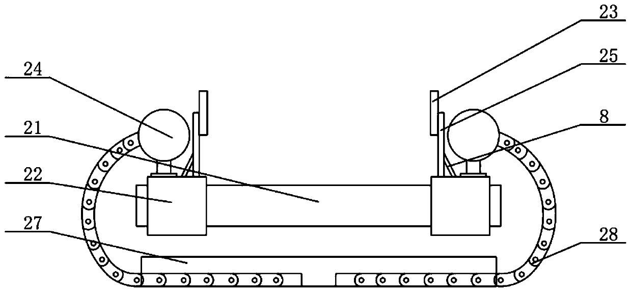
[0024] The limiting device 2 includes a connecting chute 21, a slide block 22, a lim...


PUM


Abstract

The invention discloses a limiting and fixing device for a bending machine, and relates to the technical field of manufacturing of bending machines. The limiting and fixing device comprises a plate shearing machine main body, a limiting device, a movable plate, an upper mold, a lower mold, a material supporting device, and a working table, wherein a working area is arranged in the middle of the front part of the plate shearing machine main body, the movable plate is arranged the upper part of the front part of the plate shearing machine body, the movable plate is connected with a hydraulic device of the plate shearing machine body, the upper mold is connected under the movable plate, the working table is arranged on one side of the working area, the lower mold is arranged right on the working table, the material supporting device is arranged on the front part of the plate shearing machine main body, and the limiting device is arranged on the inner side of the working table. The limiting and fixing device has the advantages that the structure is simple, a plate can be limited and fixed without manual operation of labor, and the occurrence of safety accidents is avoided while the bending quality of the plate is ensured.

Description

technical field [0001] The invention relates to the technical field of bending machine manufacturing, in particular to a position limiting and fixing device of a bending machine. Background technique [0002] A bending machine is a machine capable of bending thin plates. It includes a bracket, a workbench and a bending mechanism. Waiting for the bending parts to realize the bending operation; the bending mechanism is the core component of the bending machine, and the control of the bending mechanism is the core factor to ensure the quality of the bending operation of the bending machine. Now the bending mechanism is generally driven by an oil cylinder, controlled by guide rails and screws. The oil cylinder is connected to the guide rail plate, and the guide rail plate and the guide rail are connected by screws. Guided movement. [0003] However, there is no limit fixing device installed on the bending machine at present, so when bending, it is necessary to manually stabili...

Claims


Application Information

Patent Timeline
Patent Type & Authority Applications(China)
IPC IPC(8): B21D5/04B21D43/00
CPCB21D5/002B21D5/04
Inventor 马振东
Owner 南通福马重型机床制造有限公司
Why Eureka
Try Eureka