Four-face enclosed box bending mold and using method thereof

A technology for bending dies and bounding boxes, which is applied in forming tools, manufacturing tools, metal processing equipment, etc., can solve the problems of workpiece affecting positioning accuracy and high labor intensity, so as to improve processing efficiency, high degree of automation, and expand processing range. Effect

Active Publication Date: 2017-02-22
ANHUI LIYUAN NUMERICAL CONTROL CUTTING TOOL & PATTERNS MFG
View PDF7 Cites 2 Cited by
  • Summary
  • Abstract
  • Description
  • Claims
  • Application Information

AI Technical Summary

Problems solved by technology

However, judging from the technical solution disclosed in the patent, as the upper mold moves downward, the left and right ears gradually become wider, which means figure 1 The semi-finished workpiece shown must be put into the left and right ears when the upper mold is at a higher position, and then the semi-finished workpiece and the upper mold are lowered synchronously until they touch the lower mold to complete the bending; the defect of this scheme is obvious, the workpiece is falling The positioning accuracy is easily affected by vibration during the process, and workers need to lift the workpiece with high labor intensity, etc.

Method used


Image

  • Four-face enclosed box bending mold and using method thereof
  • Four-face enclosed box bending mold and using method thereof
  • Four-face enclosed box bending mold and using method thereof

Examples


Embodiment 1

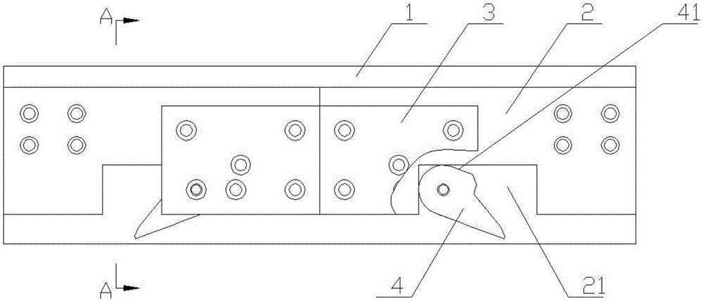
[0048] Such as Figure 8 As shown, a four-sided box body bending mold includes an upper mold and a lower mold, such as image 3 As shown, the upper mold includes an upper mold base 1, two upper mold knives 2 symmetrically arranged left and right, a rotary knife seat 3 and a rotary knife 4; the upper mold knives 2 are fixedly arranged on the upper mold base 1 outside; the lower end of the upper mold knife 2 is provided with a rotating chamber 21; the rotating knife seat 3 is fixed on the outer side of the upper mold knife 2, and one end thereof extends to the rotating chamber 21; The said rotary knife 4 is arranged in the said rotary chamber 21, as Figure 5 shown, and is rotatably and fixedly arranged on the said rotary tool seat 3 through the rotary pin 5;

[0049] Such as Figure 4 Shown, the upper mold knife bottom surface 23 of described upper mold knife 2 is an inclined plane, and the included angle of this inclined plane and horizontal plane is 5 °; The included angle...

Embodiment 2

[0061] A box bending mold surrounded by four sides is basically the same as in Example 1, the difference is that in Example 1, the rotary knife 4 still has the problem that the downward movement is not limited, which leads to the need for manual assistance in its upward movement in the next processing. Here, the rotary knife 4 in this embodiment also includes a downward stopper 42 and an avoidance cavity 43; the lower end of the upper mold knife 2 faces a corner of the rotary cavity 21 to set a limit protrusion 22; the downward stopper 42 Corresponding to the limiting protrusion 22, when the rotary knife 4 is at the lowest position, the two contact;

[0062] In addition, the upper mold knife bottom surface 23 of the upper mold knife 2 described in the present embodiment is an inclined plane, and the angle between the inclined plane and the horizontal plane is 3°; the rotary knife bottom surface 44 of the described rotary knife 4 is an inclined plane, and the inclined plane and ...


PUM


Abstract

The invention discloses a four-face enclosed box bending mold and a using method thereof and belongs to the field of bending molds. The problems that in the prior art, during bending forming of specified structures, the bending precision is poor, and the labor intensity is high are solved. The mold comprises an upper mold body which comprises an upper mold base, an upper mold tool, a rotary tool base and a rotary tool. The upper mold tool is fixed to one side of the upper mold base. A rotary cavity is formed in the lower end of the upper mold tool. The rotary tool base is fixed to the outer side of the upper mold tool, and one end of the rotary tool base stretches out of the rotary cavity. The rotary tool is arranged in the rotary cavity and rotatably and fixedly arranged on the rotary tool base. By adoption of the mold, the bending precision can be effectively improved, the convenience of operation is improved, and therefore the production efficiency is improved, and the machining efficiency and quality can be further improved.

Description

technical field [0001] The invention belongs to the field of bending molds, and in particular relates to a bending mold surrounding a box body on four sides and a use method thereof. Background technique [0002] The bending die is a die used on the bending machine to bend the sheet metal workpiece into a preset shape. There are many kinds of bending molds, which are suitable for products with various bending shapes. Even for products with the same bending shape, the bending molds are different. For the consideration of bending efficiency, bending quality and other aspects, the same Molds for curved products are also being continuously improved. [0003] Such as figure 1 Shown is a semi-finished workpiece surrounded by a box on four sides, figure 2 is its bottom view, from figure 2 It can be seen from the figure that the left and right sides of the semi-finished workpiece have been bent into a semi-enclosed shape. The next step is to bend the upper and lower sides into...

Claims


Application Information

Patent Timeline
Patent Type & Authority Applications(China)
IPC IPC(8): B21D37/10B21D5/06
CPCB21D5/06B21D37/10
Inventor 张迎年张一帆王克文张先进
Owner ANHUI LIYUAN NUMERICAL CONTROL CUTTING TOOL & PATTERNS MFG
Why Eureka
Try Eureka