
Quick drill bit replacing mechanism for drilling machine

A drilling machine and drill bit replacement technology, which is applied to metal processing machinery parts, clamping, support, etc., can solve the problems of lack of automation and replacement, and achieve the effect of improving processing efficiency

Active Publication Date: 2020-01-10
芜湖挺优机电技术有限公司
View PDF5 Cites 12 Cited by
  • Summary
  • Abstract
  • Description
  • Claims
  • Application Information

AI Technical Summary

Problems solved by technology

[0002] Drilling machine refers to the collective name of machinery and equipment that leaves cylindrical holes or holes on the target by means of rotary cutting or rotary extrusion with a tool that is harder and sharper than the target. It is also called a drill, hole puncher , Drilling machine, through-hole machine, etc., to achieve the desired effect by drilling precision parts. Drilling machines include semi-automatic drilling machines and Fully automatic drilling machine , with the increase of human resource costs, most companies consider fully automatic drilling machines as the development direction. In the field of mechanical processing, it is often necessary to drill holes through drilling machines. Drilling holes with different diameters needs to be replaced manually, and there is no automatic follow-up change, which leads to processing efficiency. Therefore, we propose a quick follow-up drill bit mechanism for drilling machines to solve the above-mentioned problems.

Method used


Image

  • Quick drill bit replacing mechanism for drilling machine
  • Quick drill bit replacing mechanism for drilling machine
  • Quick drill bit replacing mechanism for drilling machine

Examples


Embodiment Construction

[0022] The technical solutions of the present invention will be further described below in conjunction with the accompanying drawings and through specific implementation methods.

[0023] Wherein, the accompanying drawings are only for illustrative purposes, showing only schematic diagrams, rather than physical drawings, and should not be construed as limitations on this patent; in order to better illustrate the embodiments of the present invention, some parts of the accompanying drawings will be omitted, Enlargement or reduction does not represent the size of the actual product; for those skilled in the art, it is understandable that certain known structures and their descriptions in the drawings may be omitted.

[0024] In the drawings of the embodiments of the present invention, the same or similar symbols correspond to the same or similar components; , "inner", "outer" and other indicated orientations or positional relationships are based on the orientations or positional ...


PUM


Abstract

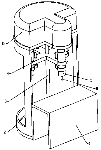
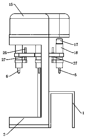
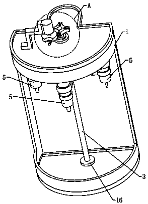
The invention relates to the technical field of drilling machines, in particular to a quick drill bit replacing mechanism for a drilling machine. The quick drill bit replacing mechanism comprises a processing table and also comprises a supporting rack located on one side of the processing table. The supporting rack is arranged vertically, a vertically arranged rotating rod is arranged in the supporting rack, a rotating plate is arranged on the rotating rod, drilling machines uniformly distributed around the circumferential direction of the rotating rod are arranged on the rotating plate, the working ends of the drilling machines are provided with drill bits of different diameters, separately, the drilling machines are vertically arranged, the drilling machines are separately arranged on the rotating plate in a lifting manner, the drilling machines are arranged above the processing table, a gap rotating driving assembly is arranged on the top of the supporting rack, the top of the rotating rod can penetrate the two sides of the top of the supporting rack rotatably to stretch upward, and the stretching end of the rotating rod is fixedly connected to the gap rotating driving assembly.The equipment is provided with the drilling machine with drill bits of different diameters and can use the needed drilling machines during process, so that the processing efficiency is improved.

Description

technical field [0001] The invention relates to the technical field of drilling machines, in particular to a quick follow-up drill bit mechanism for drilling machines. Background technique [0002] Drilling machine refers to the collective name of machinery and equipment that leaves cylindrical holes or holes on the target by means of rotary cutting or rotary extrusion with a tool that is harder and sharper than the target. It is also called a drill, hole puncher , drilling machine, through-hole machine, etc., to achieve the desired effect by drilling precision parts. Drilling machines include semi-automatic drilling machines and Fully automatic drilling machine , with the increase of human resource costs, most companies consider fully automatic drilling machines as the development direction. In the field of mechanical processing, it is often necessary to drill holes through drilling machines. Drilling holes with different diameters needs to be replaced manually, and the...

Claims


Application Information

Patent Timeline
IPC IPC(8): B23Q3/157
CPCB23Q3/1554B23Q3/157B23Q2003/155425
Inventor 姚国成
Owner 芜湖挺优机电技术有限公司
Learn More