HDPE plastic pipe forming equipment

A technology of molding equipment and plastic pipes, which is applied in the field of pipe processing, can solve the problems of low quality of finished products and achieve the effect of ensuring the quality of finished products

Pending Publication Date: 2020-01-10
陈全明
View PDF5 Cites 0 Cited by
  • Summary
  • Abstract
  • Description
  • Claims
  • Application Information

AI Technical Summary

Problems solved by technology

[0003] The processing of HDPE plastic pipes is generally made by extruders, but the existing HDPE plastic pipe forming equipment is limited by factors such as temperature control, and the quality of the finished products is relatively low

Method used


Image

  • HDPE plastic pipe forming equipment
  • HDPE plastic pipe forming equipment
  • HDPE plastic pipe forming equipment

Examples


Embodiment 1

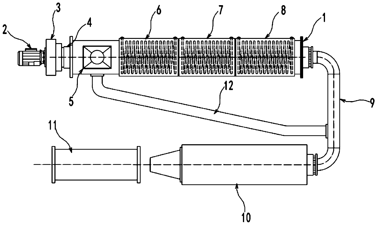
[0021] see Figure 1~2 , in the embodiment of the present invention, a HDPE plastic pipe forming equipment includes a barrel 1, a heating jacket I6, a heating jacket II7, a heating jacket III8, an extrusion die 10 and a material guide device 11,

[0022] Wherein, the barrel 1 is provided with a feeding port 5 for inputting raw materials such as HDPE powder and additives into the barrel 1, and a heating jacket I6, a heating jacket II7 and a heating jacket are installed on the outside of the barrel 1. III8, the cylinder 1 is divided into preheating section, heating section and heat preservation section, heating jacket I6, heating jacket II7 and heating jacket III8 are controlled by independent temperature control device and heat source to ensure preheating The temperature of the section, the heating section and the heat preservation section are all different. In this embodiment, the medium introduced into the heating jacket I6, the heating jacket II7 and the heating jacket III8 ...

Embodiment 2

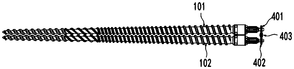
[0027] see Figure 1~3 , in the embodiment of the present invention, a HDPE plastic pipe molding equipment, the barrel 1 is installed with conical screw I101 and conical screw II102 arranged in the same direction, used for plasticizing and banburying raw materials, of course the conical screw The feeding directions of the conical screw I101 and the conical screw II102 are consistent.

[0028] Specifically, a driving motor 2 is installed at one side of the barrel 1, and the driving motor 2 drives the conical screw I101 and the conical screw II102 to rotate in the same direction and at the same speed through the reduction box 3 and the transmission box 4. Specifically: the shaft ends of the conical screw I101 and the conical screw II102 are respectively equipped with a driven gear I401 and a driven gear II402, and the driven gear I401 and the driven gear II402 are kept in mesh with the driving gear 403, and the driving gear The gear 403 is installed on the output shaft of the r...


PUM


Abstract

The invention discloses HDPE plastic pipe forming equipment and relates to the technical field of pipeline processing. The HDPE plastic pipe forming equipment comprises a machine barrel, a heating clamping sleeve I, a heating clamping sleeve II, a heating clamping sleeve III, an extrusion die and a guide device. The machine barrel is provided with a feed inlet. The heating clamping sleeve I, the heating clamping sleeve II and the heating clamping sleeve III are installed outside the machine barrel. The machine barrel is divided into a preheating section, a heating section and an insulation section. Temperatures of the heating clamping sleeve I, the heating clamping sleeve II and the heating clamping sleeve III are all controlled by independent temperature control devices and heat sources,and thus the temperatures of the preheating section, the heating section and the insulation section are all different. An end outlet of the machine barrel is connected with the extrusion die through aconnection pipe. The HDPE plastic pipe forming equipment has the beneficial effects that plastifying banburying is conducted on raw materials through two screws, the plastifying banburying effect isensured through step-type heating temperatures, when the material temperature does not reach the set threshold value, the raw materials can enter the machine barrel again to be plastified through switching of a valve, and thus quality of finished products is ensured.

Description

technical field [0001] The invention relates to the technical field of pipe processing, in particular to HDPE plastic pipe forming equipment. Background technique [0002] HDPE is a highly crystalline, non-polar thermoplastic resin. The appearance of the original HDPE is milky white, and the thin section is translucent to a certain extent. Compared with traditional pipes, HDPE plastic pipes should not only have good economy, but also have a series of advantages such as stable and reliable interface, material impact resistance, crack resistance, aging resistance and corrosion resistance. [0003] The processing of HDPE plastic pipes is generally made by extruders, but the existing HDPE plastic pipe forming equipment is limited by factors such as temperature control, and the quality of its finished products is relatively low. [0004] Based on this, the present application proposes a HDPE plastic pipe forming equipment. Contents of the invention [0005] The object of the...

Claims


Application Information

Patent Timeline
Patent Type & Authority Applications(China)
IPC IPC(8): B29C48/80B29C48/25B29C48/355B29C48/405B29C48/505B29C48/88B29C48/92B29K23/00
CPCB29K2023/065B29C48/2526B29C48/355B29C48/405B29C48/505B29C48/802B29C48/88B29C48/92B29C2948/92209
Inventor 陈全明贾建国
Owner 陈全明
Why Eureka
Try Eureka