A device for testing the dielectric properties of ice cores while drilling with the polar air drill

A technology of dielectric properties and ice cores, which is applied in the direction of measuring devices, undisturbed core extraction devices, drill bits, etc., can solve the problems of ice core data distortion, inability to perform in-situ non-destructive testing, dependence, etc., and achieve the effect of saving space

Active Publication Date: 2021-04-09
JILIN UNIV
View PDF12 Cites 0 Cited by
  • Summary
  • Abstract
  • Description
  • Claims
  • Application Information

AI Technical Summary

Problems solved by technology

Since my country launched ice core drilling activities in Antarctica in 2012, the drilling footage and ice core drilling volume have made rapid progress, but the technology in ice core detection and control analysis is not very mature, and there are single testing methods and dependence on foreign countries. equipment, and in-situ non-destructive testing and other disadvantages, we urgently need to develop a non-destructive, high-resolution ice core testing method to quickly and accurately obtain the composition and content of the ice core
At present, the methods of testing ice cores at home and abroad still only stop at taking ice cores to the surface for measurement, which leads to a large amount of distortion of ice core data
If you drill into the brittle ice area, there are highly compressed air bubbles inside the ice core, which are easily broken when taken to the surface

Method used


Image

  • A device for testing the dielectric properties of ice cores while drilling with the polar air drill
  • A device for testing the dielectric properties of ice cores while drilling with the polar air drill
  • A device for testing the dielectric properties of ice cores while drilling with the polar air drill

Examples


Embodiment Construction

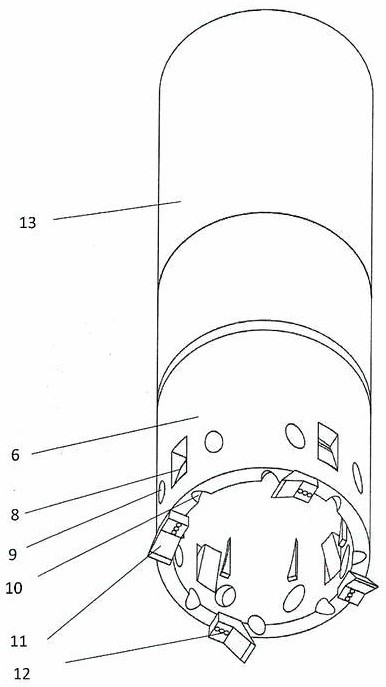
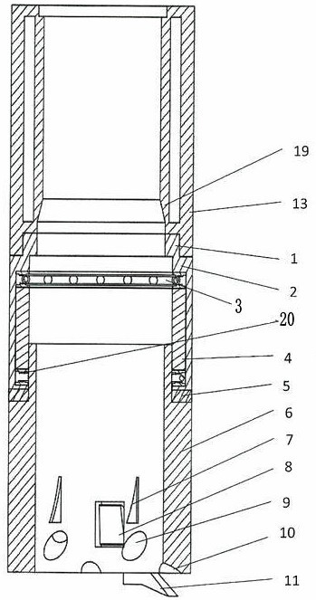
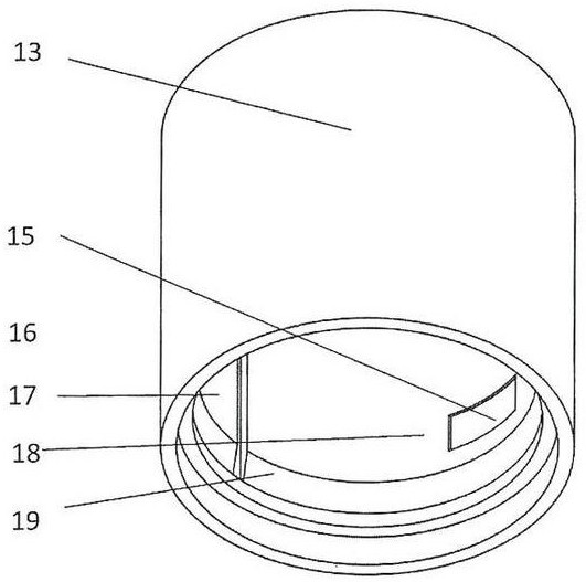
[0023] Such as figure 1 , figure 2 , image 3 and Figure 4 As shown, a device for detecting the dielectric properties of ice cores while drilling with a core-taking rotary jet drill bit in cooperation with polar air, including an upper connecting body 1, an upper bearing seat 2, an upper thrust ball bearing 3, a lower thrust ball bearing 20, and a bearing Retaining ring 4, lower bearing seat 5, drill bit body 6, diversion gas protrusion 7, ice core snap breaker 8, high-pressure air diversion hole 9, air diversion hole 10 on bottom lip surface, cutter head 11, screw 12, Ice core tube 13, wire through hole 14, lower electrode 15, middle annular gap 16, upper electrode 17, protective electrode 18 and ice core centralizer 19;

[0024] The upper connecting body 1 is threadedly connected with the ice core pipe 13;

[0025] The lower part of the upper connecting body 1 has an upper bearing seat 2, the upper bearing seat 2 is inlaid with an upper thrust ball bearing 3, the lower...


PUM


Abstract

A device for detecting the dielectric properties of ice cores while drilling with a core-taking rotary jet drill bit with polar air, the upper connecting body is connected to the ice core pipe; the upper connecting body has an upper bearing seat, and an upper thrust ball bearing is embedded in the upper bearing seat , the lower end of the upper thrust ball bearing is equipped with a bearing stop ring, the lower bearing seat is installed with a lower thrust ball bearing, the drill body is connected with the bearing stop ring, the drill body and the bearing stop ring can rotate synchronously, and the inside of the ice core tube has an ice core centralizer ;The ice core tube has a wire through hole, a low electrode, a middle annular gap, a high electrode and a protective electrode; the wall of the drill body has a guide gas protrusion, an ice core card breaker, a high pressure air guide hole, and a bottom lip surface Air guide holes, the cutter head is fixed at the bottom of the drill body. The invention can detect the dielectric properties of the ice core along with the drilling, and cooperates with the high-pressure air rotary jet drilling to avoid the influence of the liquid on the measurement accuracy. The drill bit body is single-moving, and the upper ice core tube does not rotate, which increases the stability of the drilling tool.

Description

technical field [0001] The invention is a device that can measure the dielectric properties of ice cores while drilling. In practical applications, the core-taking type rotary jet drilling can drill ice cores without drilling fluid, and the detection device while drilling can not extract ice cores to the surface for measurement. Dielectric properties of ice cores. Background technique [0002] The ice cores of the Antarctic continent are very important to people. From the obtained ice cores, the material components inside the ice cores can be analyzed, and then important information about the evolution of the Earth's ancient climate can be obtained. Since my country launched ice core drilling activities in Antarctica in 2012, the drilling footage and ice core drilling volume have made rapid progress, but the technology in ice core detection and control analysis is not very mature, and there are single testing methods and dependence on foreign countries. equipment, as well as...

Claims


Application Information

Patent Timeline
Patent Type & Authority Patents(China)
IPC IPC(8): E21B25/00E21B25/10E21B21/16E21B10/60G01R27/26
CPCE21B7/008E21B10/602E21B21/16E21B25/00E21B25/10G01R27/2623
Inventor 张楠王亮范晓鹏帕维尔达拉拉伊宫达刘昀忱王婷洪嘉琳
Owner JILIN UNIV
Why Eureka
Try Eureka