Anti-seismic structure and anti-seismic method for gyro measurement while drilling
A technology of seismic structure and gyroscope, which is used in surveying, earth-moving drilling, wellbore/well components, etc., can solve the problems of poor seismic performance, affecting the service life of equipment, and inconvenient maintenance.
- Summary
- Abstract
- Description
- Claims
- Application Information
AI Technical Summary
Problems solved by technology
Method used
Image
Examples
Embodiment 1
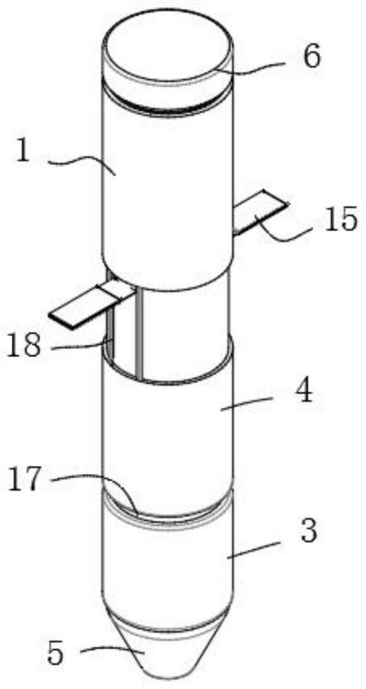
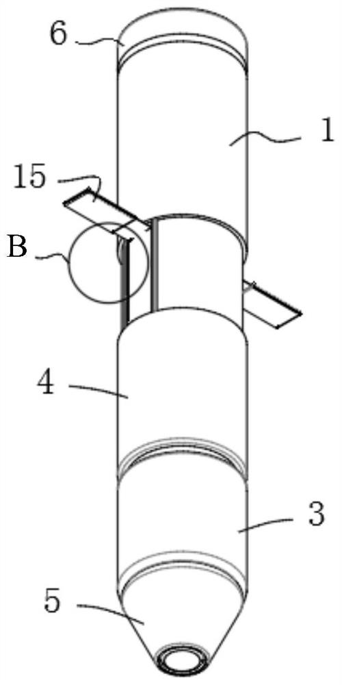
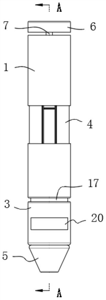
[0037] Such as Figure 1-Figure 6 As shown, the present embodiment provides a kind of anti-seismic structure for gyro measurement while drilling, including a sleeve 1, a hanging wire 10, a hanging plate 11, a pendant 8, a damping spring 9 and a damping limit block 22. The sleeve 1 Including the second section cylinder 4, the second section cylinder 4 has a section cylinder inner chamber, the lower end of the shock absorbing spring 9 is fixedly connected with the bottom surface of the section cylinder inner cavity, and the hanging plate 11 is connected to the section cylinder. The side wall of the cylinder cavity is slidingly connected, the bottom surface of the hanging plate 11 is connected with the pendant 8 through the hanging wire 10, and the bottom surface of the pendant 8 abuts against the upper end of the shock absorbing spring 9, so The hanging plate 11 is used to install the gyro measuring instrument, the damping limit block 22 is detachably connected with the side wal...
Embodiment 2
[0051] On the basis of Example 1, such as figure 1 , figure 2 , Figure 4 with Figure 5 As shown, the anti-seismic structure also includes a limiting plate assembly, the upper end of which is rotatably connected to the outer side wall of the second segment cylinder 4, and the limiting plate assembly can be rotated to the level or connected to the second The side walls of the section cylinder 4 abut against each other.
[0052] Before measurement, during equipment debugging or maintenance, the limit plate assembly can be extended to the level, and the limit plate assembly can be placed on the wellhead, so that the sleeve 1 can be positioned, the sleeve 1 can be assembled and fixed, or the inside of the sleeve 1 can be fixed. parts to adjust.
[0053] Wherein, there are at least two limiting plate assemblies, preferably, at least two limiting plate assemblies are evenly distributed in the circumferential direction of the second section cylinder 4, so that the supporting fo...
Embodiment 3
[0055] On the basis of Example 2, such as Figure 4 with Figure 5 As shown, the limiting plate assembly includes a roller shaft 16 and a limiting plate 15, and the outer wall of the second section cylinder 4 also has two vertical second slide grooves 18, and the upper end of the limiting plate 15 It is rotatably connected with the roller shaft 16 , and the two ends of the roller shaft 16 are respectively slidably connected with the corresponding second chute 18 .
[0056] The limiting plate 15 is expanded to the level, and the limiting plate 15 is placed on the wellhead, so that the sleeve 1 can be positioned. The roller shaft 16 is positioned after sliding along the second chute 18, and the height of the limit plate 15 can be adjusted, thereby adjusting the positioning height of the sleeve 1 and increasing the operational adaptability. When measuring while drilling, the limit plate 15 is rotated to abut against the side wall of the second section cylinder 4 and positioned ...
PUM
 Abstract
Description
Claims
Application Information
 - R&D
- Intellectual Property
- Life Sciences
- Materials
- Tech Scout
- Unparalleled Data Quality
- Higher Quality Content
- 60% Fewer Hallucinations
Browse by: Latest US Patents, China's latest patents, Technical Efficacy Thesaurus, Application Domain, Technology Topic, Popular Technical Reports.
© 2025 PatSnap. All rights reserved.Legal|Privacy policy|Modern Slavery Act Transparency Statement|Sitemap|About US| Contact US: help@patsnap.com


