Supercharge Your Innovation With Domain-Expert AI Agents!

Cycle valve structure

A valve and valve core technology, applied in tire inflation valve, functional valve type, tire parts and other directions, can solve the problems of short service life, poor valve sealing, etc., to reduce difficulty, improve sealing effect, and achieve good sealing. Effect

Active Publication Date: 2020-01-10
GEELY AUTOMOBILE INST NINGBO CO LTD +1
View PDF7 Cites 0 Cited by
  • Summary
  • Abstract
  • Description
  • Claims
  • Application Information

AI Technical Summary

Problems solved by technology

[0005] The purpose of the present invention is to solve the above-mentioned problems in the existing technology, and propose a valve structure. The technical problem to be solved by the present invention is: how to solve the problems of poor sealing and short service life of the existing valve

Method used


Image

  • Cycle valve structure
  • Cycle valve structure

Examples


Embodiment Construction

[0026] The following are specific embodiments of the present invention and in conjunction with the accompanying drawings, the technical solutions of the present invention are further described, but the present invention is not limited to these embodiments.

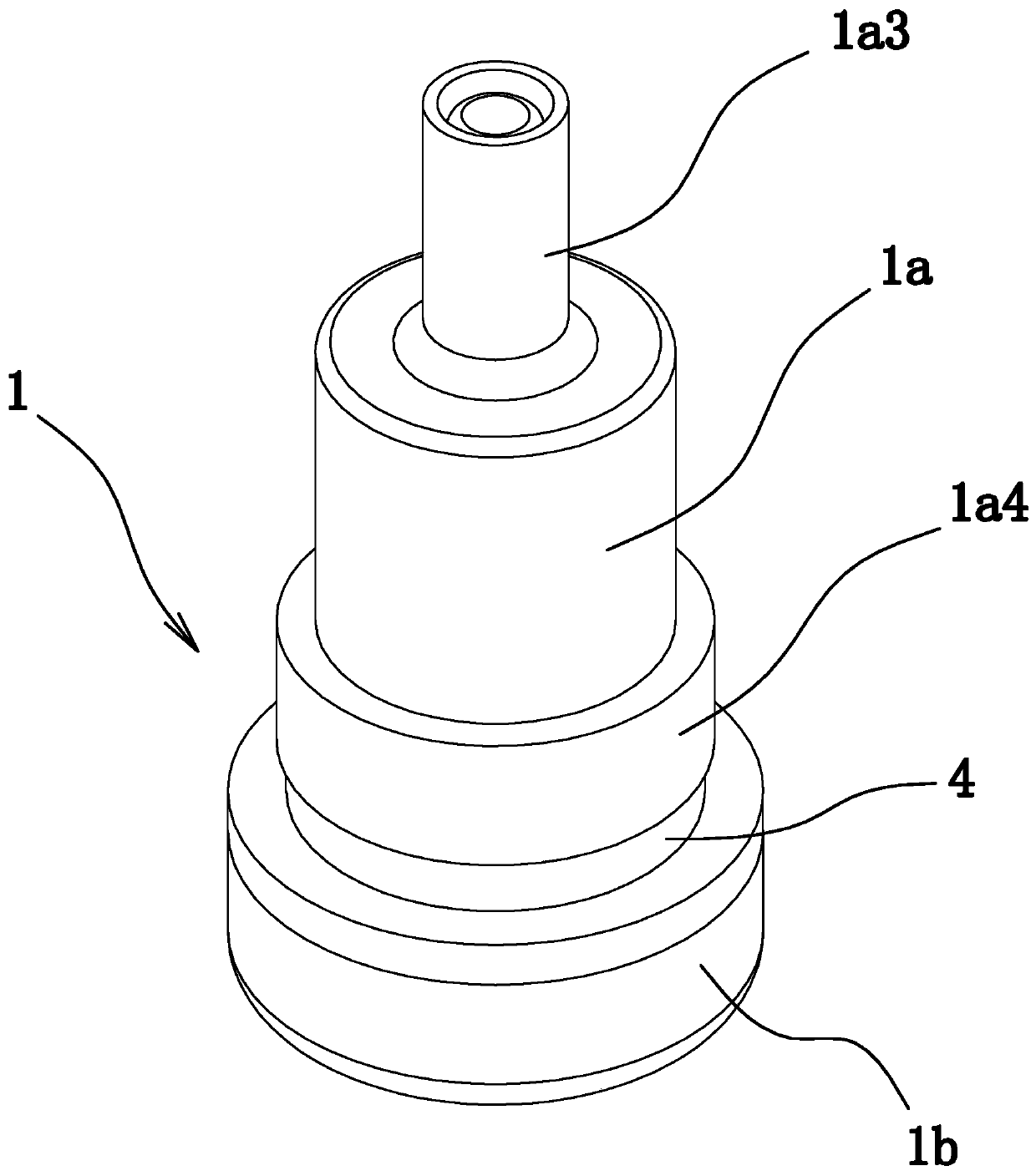
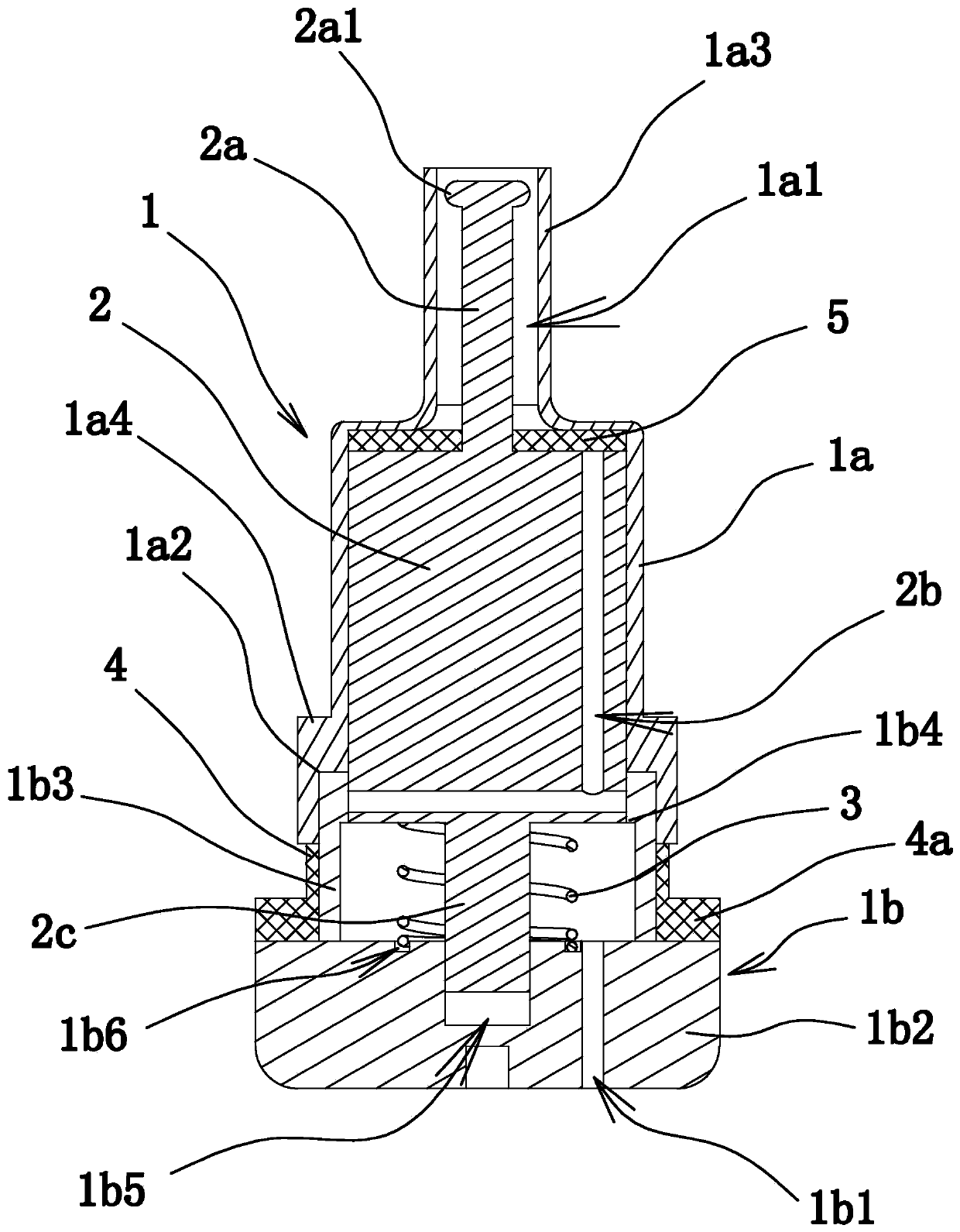
[0027] Such as figure 1 and 2 As shown, the valve structure includes a spring 3, a valve core 2 and a cylindrical housing 1. The housing 1 includes a base 1b and an upper shell 1a. The top of the upper shell 1a has an air inlet 1a1. The bottom of the upper shell 1a is connected to the base 1b in a detachable and sealed manner. The base 1b has an air outlet 1b1.

[0028] Specifically, the upper shell 1a is cylindrical, the base 1b includes a block-shaped bottom plate 1b2 and a cylindrical connecting cylinder 1b3, and the air outlet 1b1 is opened on the bottom plate 1b2. One end of the connecting cylinder 1b3 is fixed on the bottom plate 1b2, and the other end extends into the upper shell 1a and is threadedly connected wit...


PUM


Abstract

The invention provides a cycle valve structure and belongs to the technical field of machines. Through the cycle valve structure, the problems that an existing cycle valve structure is poor in sealingperformance and short in service life are solved. The cycle valve structure comprises a spring, a valve core and a tubular shell. The top end of the shell is provided with an air inlet. The bottom end of the shell is provided with an air outlet. The valve core is slidably arranged in the shell. The outer peripheral wall of the valve core abuts against the inner wall of the shell in a sealing mode. The valve core is provided with an air channel. The air inlet end of the air channel penetrates through the top end of the valve core, and the air inlet end of the air channel and the air inlet arearranged in a staggered mode. The air outlet end of the air channel can communicate with the air outlet. The two ends of the spring abut against the shell and the valve core. Under the action of the spring, the valve core abuts against the top wall of an upper shell body in a sealing mode. By simplifying the matched structure between the valve core and the shell, the influence of abrasion is eliminated, multiple sealing structures are formed between the valve core and the shell, the sealing effect is improved, and the service life is prolonged.

Description

technical field [0001] The invention belongs to the technical field of machinery and relates to a valve structure. Background technique [0002] The valve is a one-way valve installed on the wheel hub to inflate and deflate the tire. When it is opened, the gas enters the space of the tubeless tire or inner tube, and then automatically closes and seals the gas to generate air pressure to prevent the gas from escaping the tire or inner tube. [0003] Existing valve structure, such as Chinese patent application (application number: 201410793994.7) a kind of valve, comprises the valve body that has inlet passage, one end of inlet passage is inlet end, and the other end is outlet end, described The valve body is provided with a valve core inserted into the air intake passage, and an adjustment screw connected with the valve body thread is provided at the outlet end of the air intake passage. There is a control spring between the cores, and an annular tapered groove and a tapere...

Claims


Application Information

Patent Timeline
IPC IPC(8): F16K15/20F16K15/18B60C29/06
CPCB60C29/06F16K15/18F16K15/20
Inventor 蒋守国李月明
Owner GEELY AUTOMOBILE INST NINGBO CO LTD
Features
  • R&D
  • Intellectual Property
  • Life Sciences
  • Materials
  • Tech Scout
  • Unparalleled Data Quality
  • Higher Quality Content
  • 60% Fewer Hallucinations
Learn More