
Electric power inspection unmanned aerial vehicle path planning method based on improved APF

A path planning, power inspection technology, applied in non-electric variable control, vehicle position/route/height control, instruments, etc., can solve the problem of easily falling into local minimum points, unreachable targets, unable to cross U-shaped obstacles, etc. problem, to achieve the effect of good inspection effect

Active Publication Date: 2020-01-10
HEFEI UNIV OF TECH
View PDF4 Cites 3 Cited by
  • Summary
  • Abstract
  • Description
  • Claims
  • Application Information

AI Technical Summary

Problems solved by technology

[0006] The traditional artificial potential field method only considers the attraction and repulsion of the target point and obstacles in the path planning environment of the robot. Most of the improved artificial potential field methods also focus on solving the problems of local minima and target inaccessibility, requiring only The robot can avoid obstacles and reach the target point smoothly, and there is no requirement for the path the robot takes
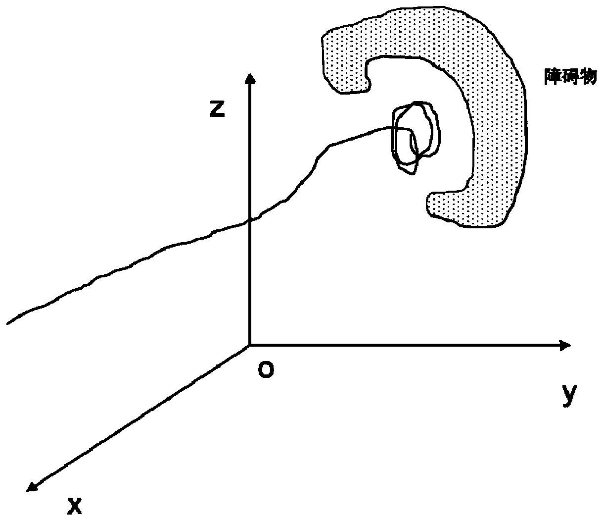
[0007] In addition, UAVs fly according to the traditional potential field, and there are problems that they are easy to fall into local minimum points and cannot pass through U-shaped obstacles.

Method used


Image

  • Electric power inspection unmanned aerial vehicle path planning method based on improved APF
  • Electric power inspection unmanned aerial vehicle path planning method based on improved APF
  • Electric power inspection unmanned aerial vehicle path planning method based on improved APF

Examples


Embodiment Construction

[0031] It should be noted that, in the case of no conflict, the embodiments in the present application and the features in the embodiments can be combined with each other. The present invention will be described in detail below with reference to the accompanying drawings and examples.

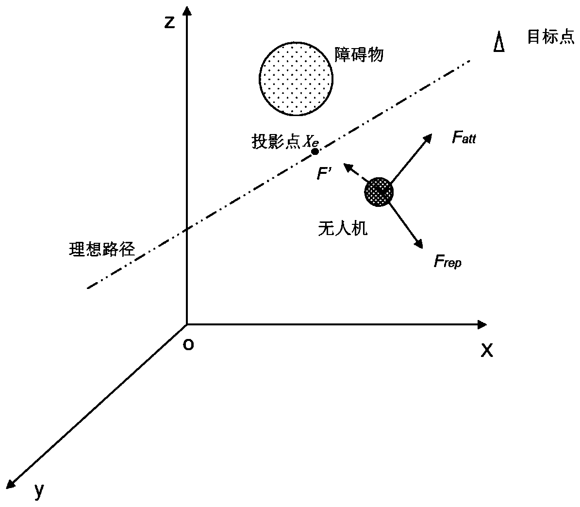
[0032] On the basis of the traditional potential field, the gravitational field U' of the projected point of the UAV on the ideal path is added, such as figure 1 Shown, F att is the attractive force generated by the gravitational field, F rep is the repulsive force produced by the repulsive field, F' is the attractive force produced by the gravitational field of the added projection point, and the improved potential field function is:

[0033] u total =U att + U rep +U'-------------(1)

[0034] U in the above formula total is the force field, U att is the gravitational field, U rep is the repulsive force field, U’ is the projection point X of the UAV on the ideal path e gravitational ...


PUM


Abstract

The invention discloses an electric power inspection unmanned aerial vehicle path planning method based on an improved APF (Artificial Potential Field). The method comprises the steps that an unmannedaerial vehicle flies along an ideal path and meanwhile senses obstacles; whether an obstacle exists within a sensing range or not is judged, and when the obstacle exists, the improved APF is adoptedfor obstacle-avoiding flight; then whether the distance between the unmanned aerial vehicle and the ideal path is smaller than a set value or not is judged, and when the distance is smaller than the set value, the unmanned aerial vehicle returns to the ideal path, and an inspection task is ended; and the unmanned aerial vehicle flies along the ideal path or returns to the ideal path to fly till the inspection task is ended. According to the method, a gravitational field of the unmanned aerial vehicle at an ideal projection point is introduced, and an action range is set; when the distance between the unmanned aerial vehicle and the ideal path is smaller than d<0>, the gravitational field is zero, and therefore repeated oscillation of the unmanned aerial vehicle nearby the ideal path is avoided; and when the unmanned aerial vehicle is trapped in a U-shaped obstacle, the exploration range of the unmanned aerial vehicle is adjusted to limit the gravity at a target point and adjust the gravity at the projection point to be zero, so that the unmanned aerial vehicle gets rid of a U-shaped region.

Description

technical field [0001] The invention relates to a path planning method for an electric power inspection unmanned aerial vehicle based on an improved APF. Background technique [0002] With the development of drone technology, drones are more and more widely used in power inspections, and the autonomous inspection of drones is becoming more and more important. Therefore, the path planning of drones around power towers is very important. . [0003] In the application of UAV in power inspection, the pilot usually controls the operation of UAV. Not only is it time-consuming and labor-intensive, but the accuracy is not high, it is easy to cause a large number of useless photos, and the quality of the work is not easy to guarantee. With the development of image processing and computer technology, the autonomous inspection of drones is becoming more and more extensive. [0004] UAV autonomous inspection means that the inspection environment is known, the trajectory is planned in...

Claims


Application Information

Patent Timeline
Patent Type & Authority Applications(China)
IPC IPC(8): G05D1/10
CPCG05D1/101
Inventor 苗东东王庆徐海明吕品
Owner HEFEI UNIV OF TECH
Learn More