
An anti-collision method for dismantling the cantilever beam tie rod of ship unloader

A technology of ship unloader and pull rod, which is applied in loading/unloading, transportation and packaging, etc., which can solve the problems of difficulty in erection, great safety hazards, and the possibility of platform crashing

Active Publication Date: 2020-05-01
MCC5 GROUP CORP SHANGHAI
View PDF8 Cites 0 Cited by
  • Summary
  • Abstract
  • Description
  • Claims
  • Application Information

AI Technical Summary

Problems solved by technology

The elevation of the hinge of the tower tie rod is about 55m. It is difficult to set up a cantilevered operation platform here, and there are great safety hazards; at the moment when the gas cuts off the tie rod, the crane arm falls under the force of gravity, and the tie rod collides with the operation platform, which is very likely to hit the platform. Measures Failure, people fall; the crane is standing on the wharf, hoisting the upper end of the tie rod at a certain angle, because the door leg of the ship unloader limits the angle of the crane arm and the hoisting space, and the downward impact force is huge when the tie rod is cut off by air ( The weight of the tie rod is about 18t), and the crane arm falls down rapidly due to the gravity. Due to the elasticity of the crane arm, it bounces up again and repeats several times. safety risk, and the crane arm may also be broken
The 300t crane needs to remove the front tie rods on both sides of the cantilever girder, and repeat the above work, which increases the frequency of danger
[0009] Therefore, there are many inconveniences and safety risks in the known technology. There are huge safety hazards in the erection of the cantilever platform, the tie rod pin lug plate at the gas cutting tower, and the lifting and removal of the car.

Method used


Image

  • An anti-collision method for dismantling the cantilever beam tie rod of ship unloader
  • An anti-collision method for dismantling the cantilever beam tie rod of ship unloader
  • An anti-collision method for dismantling the cantilever beam tie rod of ship unloader

Examples


Embodiment Construction

[0031] Exemplary embodiments of the present disclosure will be described in more detail below with reference to the accompanying drawings. Although exemplary embodiments of the present disclosure are shown in the drawings, it should be understood that the present disclosure may be embodied in various forms and should not be limited by the embodiments set forth herein. Rather, these embodiments are provided for more thorough understanding of the present disclosure and to fully convey the scope of the present disclosure to those skilled in the art. It should be noted that, in the case of no conflict, the embodiments of the present invention and the features in the embodiments can be combined with each other. The present invention will be described in detail below with reference to the accompanying drawings and examples.

[0032] The 1000t floating crane is in the direction perpendicular to the cantilever girder. It is difficult to lift the cantilever girder upwards. The pitchin...


PUM


Abstract

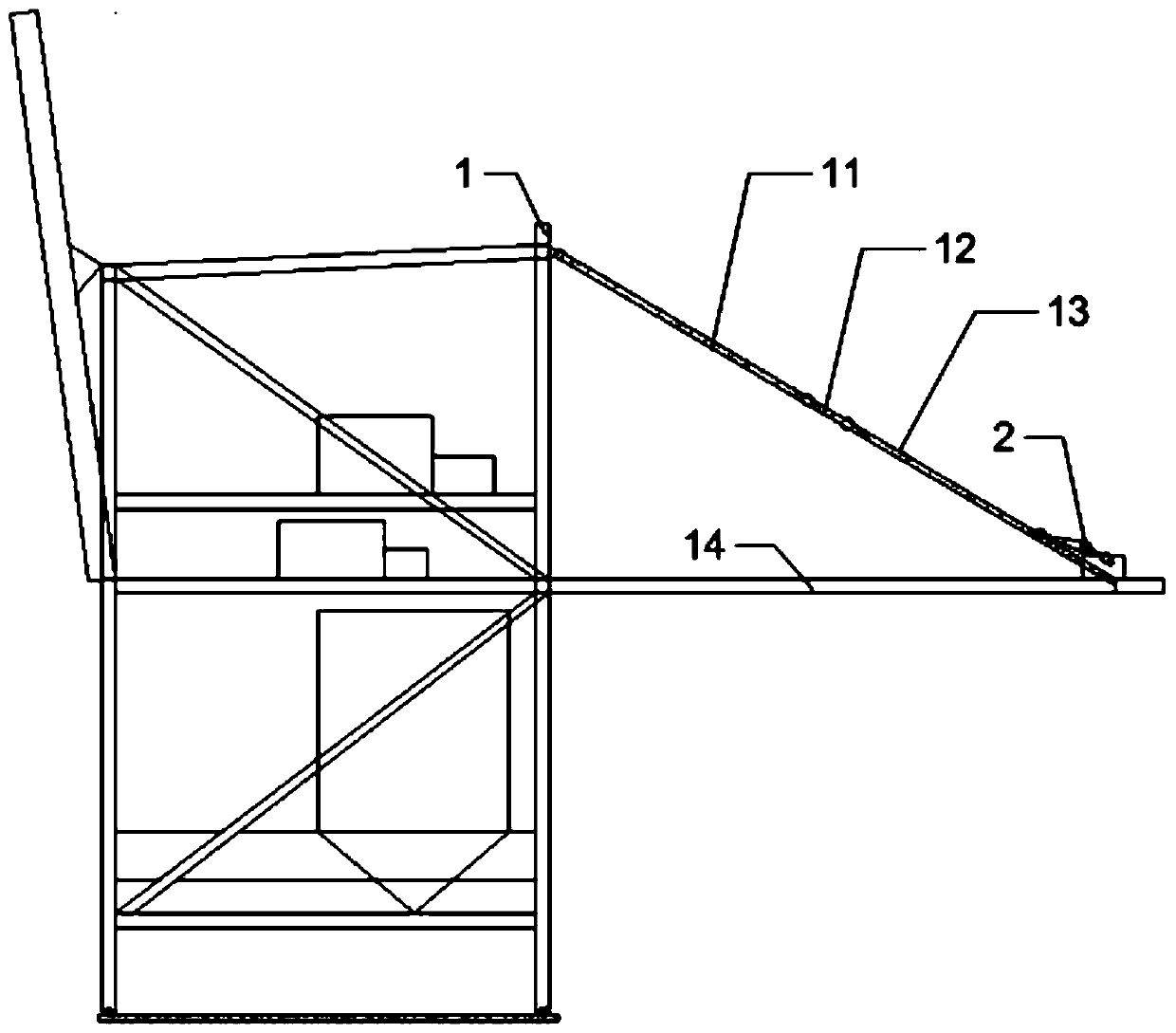
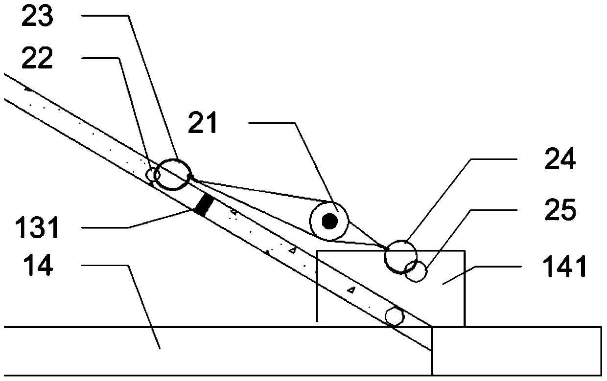
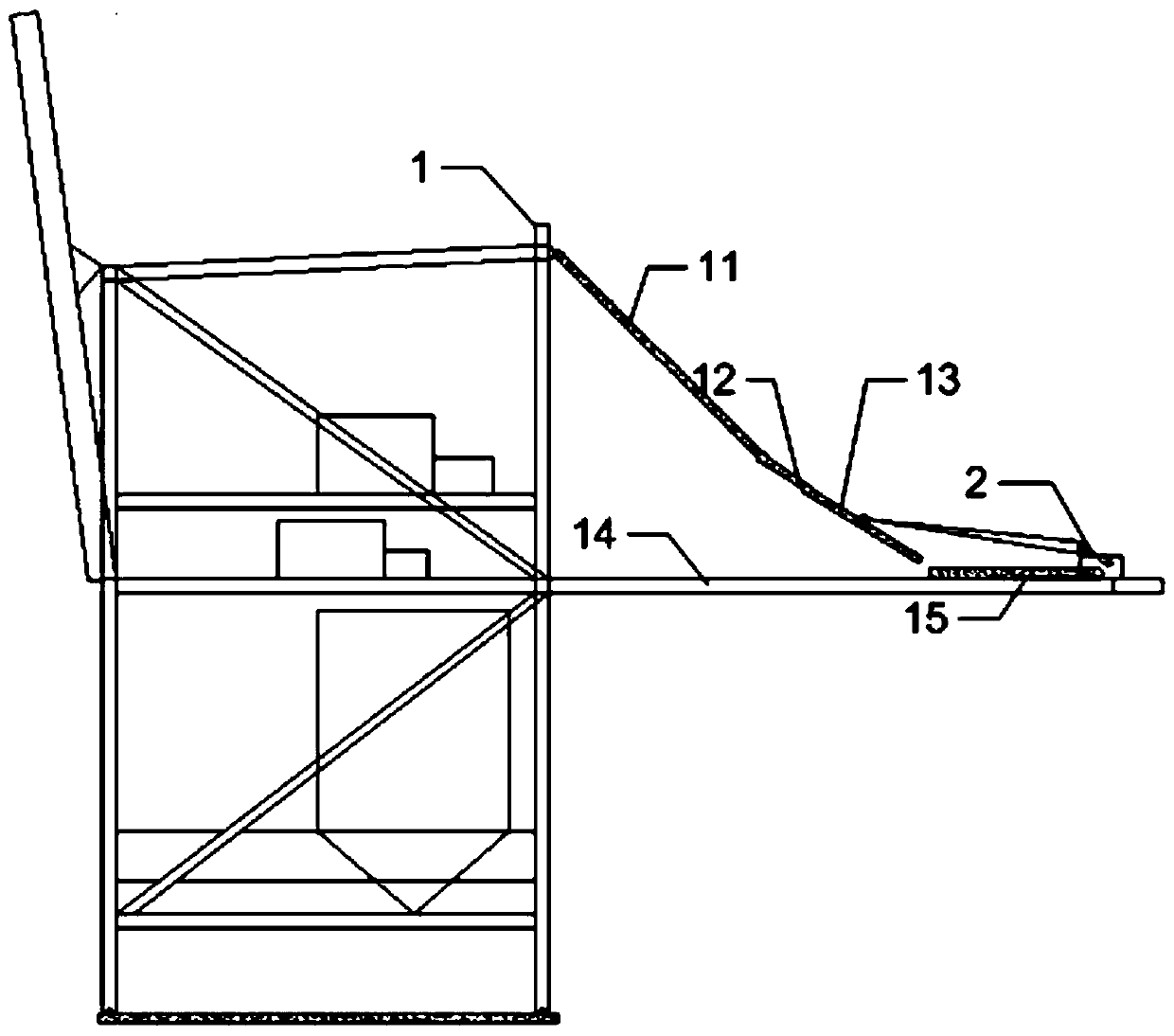
The invention provides an anti-collision method for dismounting a ship unloader cantilever girder pull rod. The method is characterized by comprising the steps that S1, a cantilever girder is difficult to hoist through a floating crane, and the pull rod is unloaded; S2, a chain block is mounted on the cantilever girder, and a hook of the chain block is hung on the cantilever girder; S3, the other hook of the chain block is hung on the pull rod; S4, the pull rod is subjected to gas cutting piecewise, and the chain block is slowly released until the pull rod stops sliding on the cantilever girder; and S5, the step S3 and S4 are repeated until the degree of an included angle between the pull rod and the cantilever girder reaches a predetermined angle. According to the method provided by the invention, the multiple buffering modes of friction force between the chain block and a pole plate and the like are fully used, gradual stepwise buffering is performed hierarchically, the recover impact force after the pull rod is cut off is always under control, the problems of impacting and rebounding during hoisting and dismounting of the pull rod are solved, and dismounting operation safety and hoisting and dismounting are under control.

Description

technical field [0001] The invention relates to the field of port mechanical equipment dismantling and construction, in particular to an anti-collision method for dismantling a cantilever girder tie rod of a ship unloader. Background technique [0002] The cantilever ship unloader is the main ship unloading equipment for bulk material and container terminals at present, and it is scattered in inland rivers and coastal terminals; its cantilever extends into the river or the coast, and a track is installed on the cantilever for the reclaiming trolley to go back and forth. The system takes material to realize the transportation conversion of the terminal and the cargo on the ship. [0003] With the frequency of use and operating conditions of the ship unloader, the steel structure will be corroded, the deflection of the cantilever girder will exceed the standard, cracks will occur in the main stress-bearing components such as the girder and the large diagonal brace of the door ...

Claims


Application Information

Patent Timeline
Patent Type & Authority Patents(China)
IPC IPC(8): B65G67/60
CPCB65G67/60
Inventor 李正波于景峰张峰袁正清
Owner MCC5 GROUP CORP SHANGHAI
Learn More