Permanent magnet generator with forward and negative rotors

A permanent magnet generator and dual rotor technology, applied in electromechanical devices, electrical components, electric components, etc., can solve the problems of restricting the development prospect of low-speed power generation, less electricity, and low rotor speed, so as to achieve a wide range of applications and improve power generation efficiency. , the effect of relative speed increase

Pending Publication Date: 2020-01-10
张英
View PDF0 Cites 1 Cited by
  • Summary
  • Abstract
  • Description
  • Claims
  • Application Information

AI Technical Summary

Problems solved by technology

But in some new energy generators, such as wind power generators, tidal power generators, etc., due to the low speed of the rotor, the generated electricity is small, which restricts the development prospects of low-speed power generation

Method used


Image

  • Permanent magnet generator with forward and negative rotors
  • Permanent magnet generator with forward and negative rotors
  • Permanent magnet generator with forward and negative rotors

Examples


Embodiment Construction

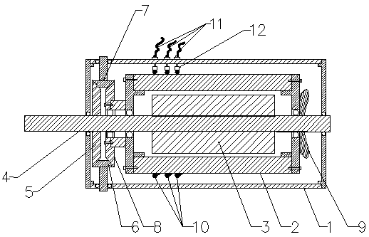
[0019] Such as figure 1 As shown, a permanent magnet generator with forward and reverse double rotors includes a casing 1, an outer rotor 2, an inner rotor 3, a central shaft 4, a driving wheel 5, a driven wheel 8, a transmission wheel 6-7 and a cooling fan 9. There is an outer rotor 2 inside the casing 1, and an inner rotor 3 is arranged inside the outer rotor 2. The inner rotor 3 is fixed on the central shaft 4 and rotates with the rotation of the central shaft 4. The outer casing 1 and the outer rotor 2 are respectively installed through bearings. On the central rotating shaft 4 , the outer rotor 2 rotates around the central rotating shaft 4 , and the rotating direction of the outer rotor 2 is opposite to that of the inner rotor 3 . A driven wheel 8 is fixedly mounted on the front end of the outer rotor 2 . A driving wheel 5 is fixedly installed on the central rotating shaft 4 in front of the driven wheel 8, and along with the central rotating shaft 4 rotates, the driven w...


PUM


Abstract

The invention relates to a permanent magnet generator with positive and negative rotors. The permanent magnet generator comprises a shell and an outer rotor, an inner rotor, a central rotating shaft,a driving wheel, a driven wheel, a transmission wheel and a heat dissipation fan which are arranged inside the shell. The outer rotor is arranged in the shell. The inner rotor is arranged in the outerrotor. The inner rotor is fixed on the central rotating shaft and rotates with the rotation of the central rotating shaft. The shell and the outer rotor are respectively installed on the central rotating shaft through bearings. The outer rotor rotates around the central rotating shaft, and the rotation direction of the outer rotor is opposite to that of the inner rotor. The permanent magnet generator has the beneficial effects that the outer rotor and the inner rotor of the double-rotor generator are driven by the driving wheel, the transmission wheel and the driven wheel to make synchronousconstant speed rotation in positive and negative directions respectively so that the relative rotation speed of the outer rotor and the inner rotor of the generator is doubled, the power generation efficiency of the generator is improved and the application range is wide.

Description

Technical field: [0001] The invention relates to a permanent magnet generator with forward and reverse double rotors, which belongs to the technical field of generators. Background technique: [0002] Existing generator is mainly made of parts such as stator, rotor, end cover, electric brush, support and bearing. The stator is composed of frame, stator core, wire wrap winding, and other structural parts that fix these parts. The rotor is composed of rotor core, rotor pole (with yoke and pole winding), slip ring, (also known as copper ring, collector ring), fan and shaft and other components. The stator and rotor of the generator are connected and assembled through the bearing, machine base and end cover, so that the rotor can rotate in the stator, and a certain excitation current is passed through the slip ring, so that the rotor becomes a rotating magnetic field, and the stator coil cuts the magnetic force line. , so as to generate an induced potential, which is drawn out...

Claims


Application Information

Patent Timeline
IPC IPC(8): H02K16/00H02K7/10H02K9/06H02K5/04H02K5/22H02K1/27H02K7/116H02K13/00
CPCH02K1/27H02K5/04H02K5/225H02K7/10H02K7/116H02K9/06H02K13/003H02K16/005
Inventor 杨道彤
Owner 张英
Why Eureka
Try Eureka