Dual-drive wind power generation signal tower

A wind power generation device and dual-drive technology, applied in the field of signal towers, can solve the problems of low wind energy utilization efficiency and achieve the effect of improving wind energy utilization rate and relative speed

Pending Publication Date: 2022-01-18
苏卫星
View PDF1 Cites 0 Cited by
  • Summary
  • Abstract
  • Description
  • Claims
  • Application Information

AI Technical Summary

Problems solved by technology

[0006] In view of the above defects, the technical problem to be solved by the present invention is to provide a dual-drive wind power signal tower to solve the problem of low utilization efficiency of wind energy in existing wind power signal towers

Method used


Image

  • Dual-drive wind power generation signal tower
  • Dual-drive wind power generation signal tower
  • Dual-drive wind power generation signal tower

Examples


specific Embodiment 1

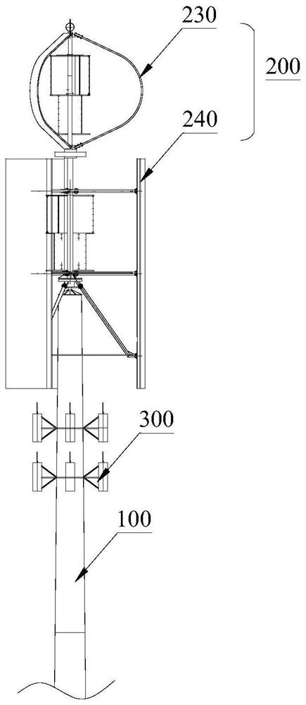
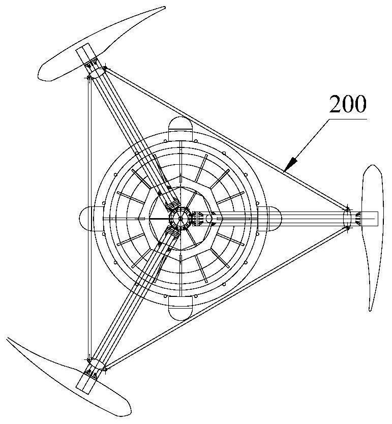
[0057] See figure 1 and figure 2 , figure 1 A schematic diagram of a signal tower for dual-drive wind power generation provided in Embodiment 1 of the present invention; figure 2 for figure 1 top view.

[0058] Such as figure 1 , figure 2 As shown, the signal tower of dual-drive wind power generation provided by the specific embodiment 1 of the present invention includes a vertically arranged tower column 100 and a dual-drive wind power generation device 200 arranged on the upper end of the tower column 100, and a fixed device around the outer periphery of the tower column 100 There are multiple sets of signal transmitting antennas 300. The transmitting antennas 300 are used to transmit communication signals of the communication base station, and the dual-drive wind power generation device 200 is used to supply power to the communication base station.

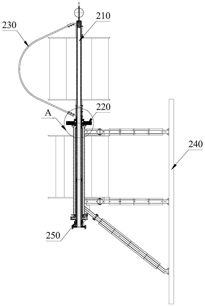
[0059] Another example image 3 as shown, image 3 It is a schematic diagram of a dual-drive wind power generation...

specific Embodiment 2

[0088] The solution provided by the specific embodiment 2 of the present invention is a further improvement made on the basis of the specific implementation 1, and the specific structure of the support seat assembly 250 is specifically refined to solve the problem of flexibility between the inner shaft 211 and the outer shaft 212. Turning and braking problems.

[0089] Such as Figure 4 , Figure 7 As shown, the support seat assembly 250 includes a base 251 , a shaft seat 252 , an intermediate shaft 253 and a braking device 254 .

[0090] The center of the base 251 has a center hole, and a first bearing 255 is arranged at the center hole, and the lower end of the inner rotating shaft 211 is rotatably arranged on the first bearing 255 .

[0091] The lower end of the shaft seat 252 is provided with a shaft seat lower flange 2521 , and the shaft seat lower flange 2521 is fixed on the base 251 . The top of the first bearing 255 is provided with a slip ring device 256, the slip ...


PUM


Abstract

The invention discloses a dual-drive wind power generation signal tower. The dual-drive wind power generation signal tower comprises a vertically-arranged tower column, a plurality of signal transmitting antennas are fixedly arranged around the periphery of the tower column, a dual-drive wind power generation device is arranged at the upper end of the tower column, the dual-drive wind power generation device comprises a fan blade shaft assembly and a generator assembly, the fan blade shaft assembly is composed of an inner rotating shaft and an outer rotating shaft arranged on the outer side of the inner rotating shaft in a sleeve mode, the generator assembly comprises a shell and a sheet winding arranged in the shell, the sheet winding and the shell are fixed to the inner rotating shaft and the outer rotating shaft correspondingly and driven by an upper fan blade assembly and a lower fan blade assembly correspondingly, and the rotating direction of the lower fan blade assembly is opposite to that of the upper fan blade assembly. According to the dual-drive wind power generation signal tower, the upper fan blade assembly and the lower fan blade assembly respectively drive the shell and the sheet winding of the generator assembly to rotate relatively, so that the relative rotating speed between the shell and the sheet winding is improved, and the wind energy utilization rate is improved.

Description

technical field [0001] The invention relates to the technical field of signal towers, in particular to a signal tower for dual-drive wind power generation. Background technique [0002] With the development of communication technology and Internet technology, mobile communication has developed into an important means of communication. In order to improve the quality of communication and increase the coverage of mobile signals, more and more signal towers need to be built as communication base stations or relay stations. [0003] The signal tower is usually arranged outdoors and powered by the grid. Since the signal tower works all the year round, it consumes a lot of energy. [0004] In order to achieve the purpose of energy saving and environmental protection, the Chinese utility model patent CN206023658U discloses an independent energy supply system for a signal transmission tower, including a column, and a wind power generation mechanism is installed on the upper end of ...

Claims


Application Information

Patent Timeline
IPC IPC(8): F03D9/25F03D3/02F03D3/06F03D15/20F03D80/70F03D13/20H02K16/00E04H12/00
CPCF03D9/25F03D3/02F03D3/005F03D3/061F03D3/064F03D15/20F03D80/70F03D13/20H02K16/005E04H12/00F03D3/062Y02E10/74Y02E10/728
Inventor 苏卫星苏志伟苏志超苏志丹
Owner 苏卫星
Why Eureka
Try Eureka