
Drums for carding machines

A technology of carding machine and drum, which is applied in the field of drum for carding machine, and can solve the problems of reducing quality, affecting thermal expansion, and being expensive

Active Publication Date: 2022-04-19
MASCHINENFABRIK RIETER AG
View PDF9 Cites 0 Cited by
  • Summary
  • Abstract
  • Description
  • Claims
  • Application Information

AI Technical Summary

Problems solved by technology

On the one hand, this will affect thermal expansion, but on the other hand, this will also reduce the mass relative to the centrifugal force generated
This embodiment is also relatively complex and expensive to manufacture

Method used


Image

  • Drums for carding machines
  • Drums for carding machines
  • Drums for carding machines

Examples


Embodiment Construction

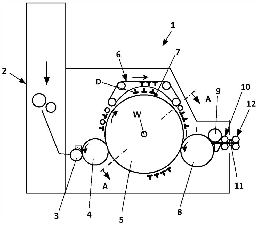
[0021] figure 1 A card 1 is shown having a feed chute 2 through which fibrous material in the form of nonwoven fibers is supplied from a feed roll 3 . From the feed roll 3 the fibrous material is sent to the licker-in roll 4, which transfers the fibrous material to the carding cylinder 5 (referred to simply as "drum") of the card 1 . Due to the rotational movement of the drum 5 around its axis (W-axis) (indicated by the arrow), the fiber material entrained by the drum 5 is displaced and enters the area of ​​the main carding zone 7 which is connected above the drum 5 Rotating rotary flat units 6 are formed in combination. The direction of rotation of the rotary flat unit 6 is indicated by an arrow. The rotating flat unit 6 is provided with a schematically shown rotating flat bar D which is equipped with a card clothing (not shown).

[0022] After the main carding section 7 , the carded fiber material enters the area of ​​a rotatably mounted doffer 8 , which transfers the fib...


PUM


Abstract

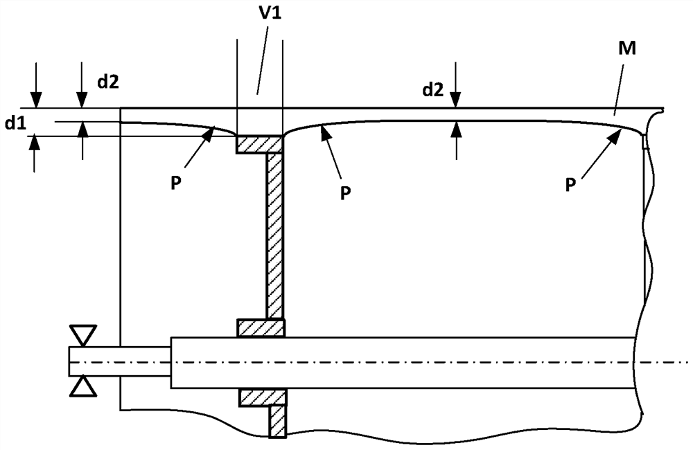
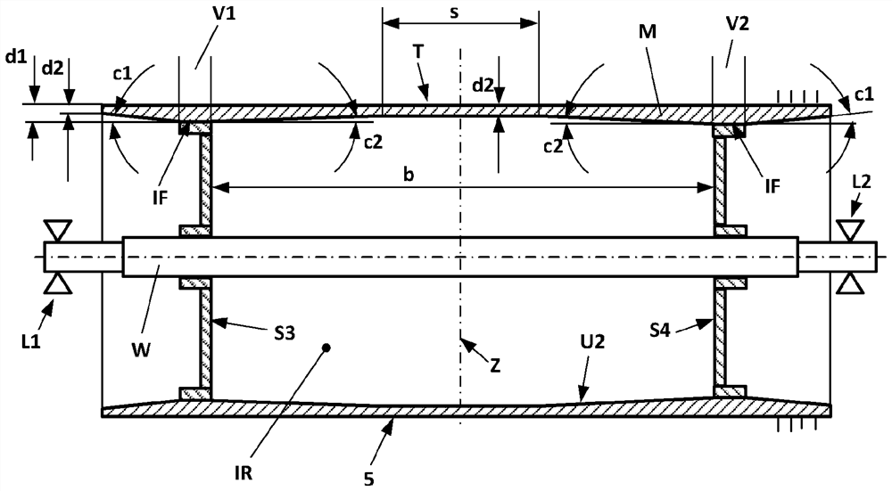
The invention relates to a cylinder (5) for a card (1) comprising a cylinder (5) having a wall thickness (a, d1, d2) and connected in an interior space (IR) to at least two spokes (S1, S2, S3, S4) of the cylindrical drum shell (M), the at least two spokes extending in radial direction and arranged at a distance (b) from each other, as seen in the axial direction of the drum (5). In order to minimize the change in the diameter range of the drum shell under high centrifugal force, it is proposed that the dimension (d1) of the wall thickness of the drum shell (M) in the connection area (V1, V2) with the corresponding spokes (S3, S4) should be smaller than The wall thickness outside this connection area (V1, V2) is greater so that, as seen in the axial direction of the drum, the wall thickness (d1) of the drum shell is at least in the area between the spokes (S3, S4) Beginning at the connection area of ​​the corresponding spokes and decreasing continuously to the minimum wall thickness (d2).

Description

technical field [0001] The invention relates to a drum for a carding machine comprising a cylindrical drum shaft having a wall thickness and connected to at least two spokes extending in radial direction in an inner space And are arranged at a distance from each other, as seen in the axial direction of the drum. Background technique [0002] In order to obtain the most efficient carding possible, the card gap must be minimized, especially the main gap between the card clothing at the top of the card and the card clothing of the card cylinder (also called cylinder or cylindrical cylinder). Carding area. The card clothing of the card cylinder is applied to the outer circumference of the card cylinder by a special winding and fastening method. In order to achieve high output, the speed of the card cylinder has been increased in recent years. In other words, card cylinders with rotation speeds greater than 600 rpm have been used simultaneously. [0003] The increase in rotat...

Claims


Application Information

Patent Timeline
Patent Type & Authority Patents(China)
IPC IPC(8): D01G15/16
CPCD01G15/16
Inventor E.梅德韦茨基
Owner MASCHINENFABRIK RIETER AG
Learn More