Diaphragm vacuum pump

A vacuum pump and diaphragm technology, applied in the direction of pump, pump control, pump components, etc., can solve the problems of diaphragm vacuum pump diaphragm aging and damage, shortening of diaphragm vacuum pump life, liquid or water vapor entering, etc., to improve condensation effect and improve service life. , the effect of increasing the duration of continuous operation

Active Publication Date: 2020-01-14
广东福雪莱电气有限公司
View PDF8 Cites 1 Cited by
  • Summary
  • Abstract
  • Description
  • Claims
  • Application Information

AI Technical Summary

Problems solved by technology

[0004] In order to make up for the deficiencies of the existing technology, the diaphragm vacuum pump in the prior art directly evacuates the device that needs to be vacuumed, and liquid or water vapor is prone to enter. At the same time, if the device is at a high temperature, the heat in the device is directly extracted Air can easily cause problems such as aging and damage to the internal diaphragm of the diaphragm vacuum pump. If corrosive liquid enters directly, it will corrode the diaphragm or seals and other components in the diaphragm vacuum pump, resulting in reduced service life or damage to the diaphragm vacuum pump, etc. , the present invention proposes a diaphragm vacuum pump

Method used


Image

  • Diaphragm vacuum pump
  • Diaphragm vacuum pump
  • Diaphragm vacuum pump

Examples


Embodiment approach

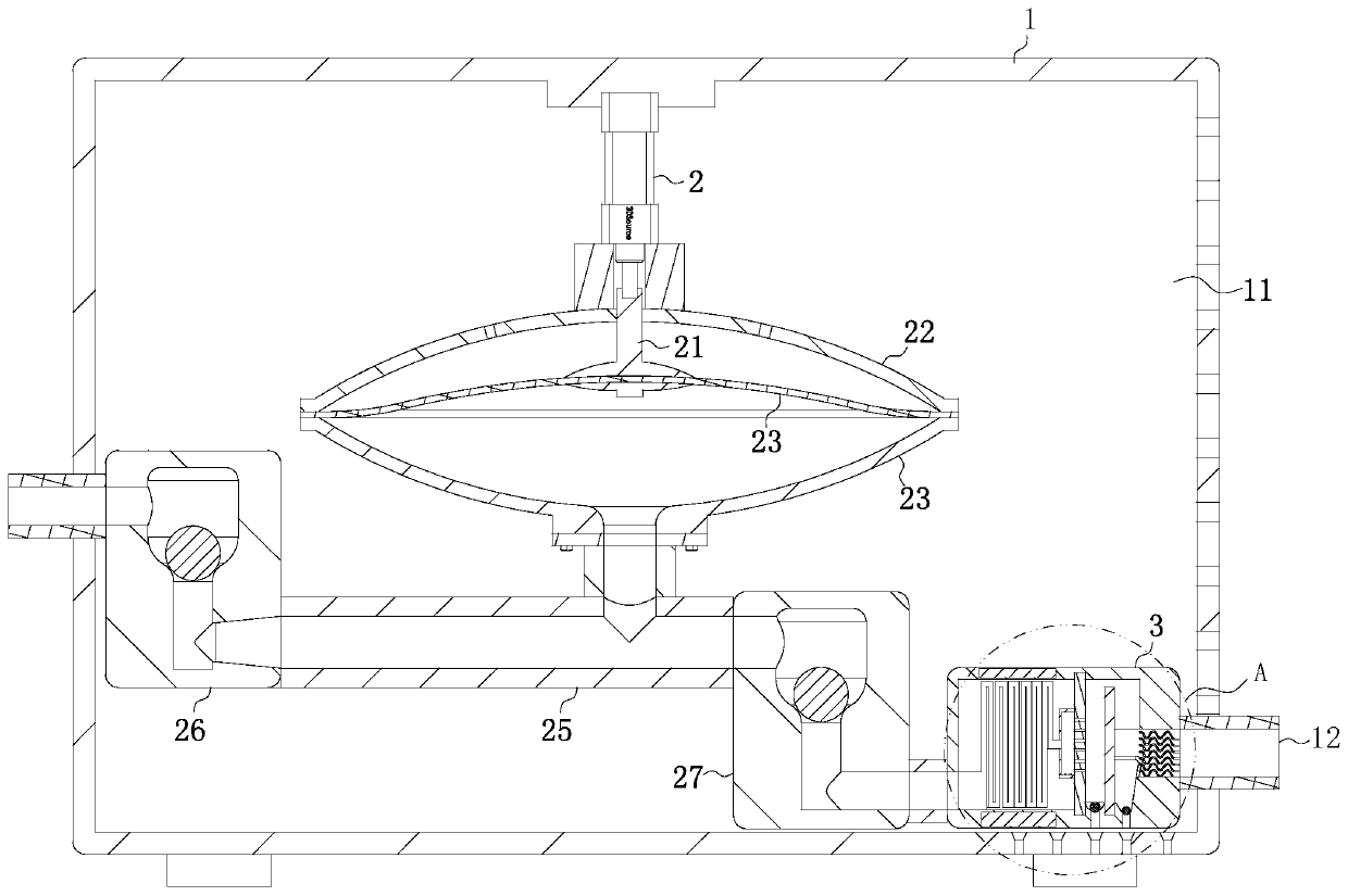
[0024] As an embodiment of the present invention, the left side of the orifice plate 31 is fixedly connected with an air-container cover 37 at the position of the air guide hole 32; two electrical connectors 38 are fixedly connected with the lower surface inside the air-container cover 37; There is a gap space between the two electrical connectors 38; during operation, when a large amount of liquid enters the diaphragm vacuum pump uncontrollably, the liquid will pass through the air guide hole 32 on the first orifice plate 31 and enter the air containment cover 37 and then further introduced into the interior of the vacuum pump next door, so in order to prevent the liquid from being further introduced through the container cover, by setting two electrical connectors 38 at the bottom of the container cover, if there is liquid flowing in, the two electrical connectors 38 will be caused by liquid When it is turned on, the electrical signal that is turned on will make the diaphragm...


PUM


Abstract

The invention belongs to the technical field of vacuum pumps, and particularly relates to a diaphragm vacuum pump. The diaphragm vacuum pump comprises a shell, an air cylinder and a protection box, ahollow cavity is formed inside the shell, the upper surface of the hollow cavity is fixedly connected with the air cylinder, an output shaft of the air cylinder is fixedly connected with a moving column, moreover, the lower surface of the moving column is fixedly connected with a diaphragm, and the protection box is arranged on the side surface of the right side of the hollow cavity. According tothe diaphragm vacuum pump, the problems that when the diaphragm vacuum pump is directly used for vacuumizing a device, a liquid or water vapor in the device is prone to be sucked into the diaphragm vacuum pump, meanwhile, under the condition that if the device is internally in the high temperature, when hot air in the device is directly extracted, the diaphragm inside the diaphragm vacuum pump isprone to being damaged and the like are effectively solved, and the service life of the diaphragm vacuum pump is effectively prolonged.

Description

technical field [0001] The invention belongs to the technical field of vacuum pumps, in particular to a diaphragm vacuum pump. Background technique [0002] Diaphragm vacuum pump, with advanced design, high working efficiency and long service life, is a replacement product integrating high technology. The supporting products of precision chromatographic instruments are also one of the necessary equipment for laboratories. [0003] In the prior art, the diaphragm vacuum pump directly evacuates the device that needs to be vacuumed, and liquid or water vapor is prone to enter. At the same time, if the device is at a high temperature, the hot air in the device is directly extracted, which is likely to cause the internal membrane of the diaphragm vacuum pump If there is a corrosive liquid directly entering, it will corrode the diaphragm or seals in the diaphragm vacuum pump, resulting in reduced life or damage to the diaphragm vacuum pump. The current existing technology deals w...

Claims


Application Information

Patent Timeline
Patent Type & Authority Applications(China)
IPC IPC(8): F04B45/053F04B37/14F04B39/16F04B39/10F04B49/10F04B39/06
CPCF04B37/14F04B39/06F04B39/10F04B39/16F04B45/053F04B49/10
Inventor 不公告发明人
Owner 广东福雪莱电气有限公司
Why Eureka
Try Eureka